Hi Everyone!
For the last year or so, I’ve been researching what all would be needed to produce something in the domain of 3D scanning for what we already have in the RepRap project. In the current state of hardware people have developed so far, there are a lot of great one-off projects that have been produced to be learned from (though they aren’t designed with easy repeatability in mind). The corresponding state of scanning software is not so good - people are are forced to use proprietary software due to lack of quality free software or open source alternatives.
Aleph Objects, Inc. has recently committed to developing a libre [hard/soft]ware 3D scanner, a project I’ve been put in charge of. What follows below are my notes on the project, primarily on the software that will be developed for it.
I’d like to lay down some constraints for this project:
- 1) The hardware must be libre hardware (with the acceptable allowance here being for standardized components that are easily sourced or replaced, eg cmos cameras).
2) The software must be free software.
3) The product needs to be < $1000
And, because LulzBot has a reputation to live up to about producing
totally awesome stuff that is actually usable to normal people, I’m
going to add:
- 4) The software’s output must be a printable stl file in the vast majority of cases. Eg generating a point cloud and telling the user to get cracking with meshlab is not ok.
With those four constraints, there is literally nothing out there in terms of existing projects that we can just manufacture and sell.
The Hardware
Early in the development process, the hardware is going to be simulated (likely using Blender), and so is less important to mention now. To be brief, it is going to be a modification of the laser-line scanner. The part that is different about this design, is that the scan area is to be contained in an enclosure.
The gist of the hardware is this:
-
- a box
- a laser + clear dowel
- a turn table
- two cameras, along the same radius from the turn tabel - one looking down slightly from above, one looking up slightly from below.
- a micro controller, maybe a BBB or an Arduino
Nothing hard to build here.
The Software
For about two or three years now I’ve been working on voxel-based slicing engine. The algorithm was originally conceived as a means of converting solid appearing (yet totally non-manifold) 3D meshes into manifold ones. While not originally intended for it, the method adapts well for scanning, because a sufficiently dense point cloud can be an example of a “solid appearing, non-manifold object”.
The algorithm for scanning assumes there is a model on a turn table, 1 or 2 cameras and a laser line in fixed locations with known orientations.
Step 0:
- Calibration is done with the scan chamber empty. For each camera, take a picture and save for future reference. This will be referred to as the [bg reference].
Step 1:
- An object is in the scan chamber. A solid voxel model is instanced, it represents the scannable area. This will be refered to as the [scan positive].
Step 2:
- For each step on the turn table, for each camera:
A: Take a picture, with the laser line off but the object lit - this will be referred to as the [scan sample].
B: The [bg reference] and the [scan sample] are used to make the [contour mask]. In a perfect world, this would be achived by subtracting the [bg reference] from the [scan sample] and taking the threshold of the result to produce a black and white bitmask [contour mask]. In reality, opencv might be useful here. Remove noise from the [contour mask], if necessary.
C: For each black pixel in the [contour mask]: Assuming the [contour mask] is the back of the viewing frustrum of the camera, cast a ray from the camera location to the pixel in the mask. Delete all voxels in the [scan positive] that intersect with the ray. This will capture all convex details of the object. Scan resolution is directly determined by the camera’s resolution.
D: Take a picture, with the laser line on but other lighting off - this will be referred to as the [line sample].
E: For every white pixel in the [contour mask] of which the corresponding pixel from the [line sample] who’s color is close to the expected color of the laser line: Use paralax to calculate the pixel’s 3D coordinates relative to the camera and laser line. Project a line from the camera to the “pixel”'s calculated 3D coordinates to the first voxel along that vector past the “pixel”. Draw voxels along the line segment between the collision and the “pixel”. May need to generate a frustrum or cone instead of a line. These new voxels are added to the [scan positive]. This will capture all concave details of the object, in a somewhat lower resolution than the convex details.
Step 3:
- At this point, the [scan positive] is a voxel model that closely resembles the topology of the object being scanned. However, interior voxels need to be removed. Thinking in terms of a cubic grid, the outter most shell of the grid needs to be completely empty. This either should be done by deleting the outter most grid “shell” from the [scan positive] (not to be confused with the outter most layer of the actual voxel data) or by doing the 3D equivalent of increasting the “canvas size” by 2 on all axies in the gimp and centering the image.
Step 4:
- Define a new, empty voxel model - called the [scan negative] - do a color fill algorithm on the [scan positive] starting from on of the corners to determine the volume of space around the scanned object. This data is added to the [scan negative].
Step 5:
- Delete the [scan positive] (or perhaps keep it to use as reference for color values). The inversion of the [scan negative] is the [scan result]. From this point, the exterior voxels may be easily identified (by their adjacent neighbors or lack thereof), and a high poly stl may be generated via marching cubes algorithm.
Step 6:
- Save result as stl.
So, thats the basic algorithm for scanning. The “casting” that happens in steps 3 and 4 might not be necessary - it mostly depends on how noisy the laser line generated voxel data is.
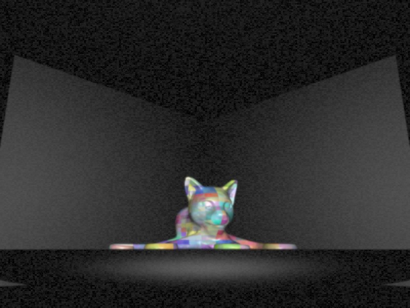
I mentioned before that the hardware of the scanner was going to be simulated at first, in Blender of all things. What is meant by that, is that the basic geometry of the scanner (as seen from the cameras’ perspectives) will be built out in blender. The object to be scanned will be parented to the turn table, and python scripting will be used to turn on/off lights, rotate the object, and capture data from the cameras. Noisy rendering settings may also be used to make things interesting.
Simulating it in this way will allow for me to tweak the design of the scanner (eg what backdrop works best for a variety of objects). It also would be fun software to release for people to play with once the algorithm is implemented, and could be useful for reparing models.