More pictures:


Is this picture an example of what the anti z wobble z nut is meant to eliminate?
edit: In response to piercet. The z-banding does line up with the threads on the lead screws.

Yes. If you hold the boat up against your leadscrews next to the cabin pillar, you will notice that the wavy pattern lines up fairly close to the threads of the leadscrew itself. If they don’t line up, it’s a different issue, usually related to layer height or periodic extruder slipping.
piercet, do you have a picture of a (maybe also white) part before and after you fitted your anti-wobble device? I think you have not posted a comparison up to now, I’m interested in seeing what’s possible 
I don’t have anything in white. Closest thing I have is the series after the Y axis upgrade was installed, which had the early version of the anti wobble fitted. https://forum.lulzbot.com/t/adjustable-heat-bed-glass-mount/38/1
I need to take some more “after” pictures and post them.
Here are some before anti wobble next to after anti wobble parts. The one on the right is with all the mods installed, the reinforced X carriage, the hexagon hotend, The X y and Z openbuilds and the Anti wobble nuts. The far right one is a stock Taz 3 nut, the blue one was with just the X axis and the Anti wobble, the middle black one is with everything except the anti wobble and the reinforced X carriage. it’s hard to tell with flash photography. it’s a very subtle difference between the last two. in person, i would say the one on the far right is the sharpest of the prints.


Its hard to see the detail on the blue object. The middle object looks really good, though.
What are you print speeds?
I generally print at about 150 mm /sec for perimiters, 185 for solid infil, much slower than that for first layers and bridging. I can push it faster than that, but I haven’t tried a long print at the higher speeds yet.
I printed a benchy boat too, just for the heck of it. 200mm / s
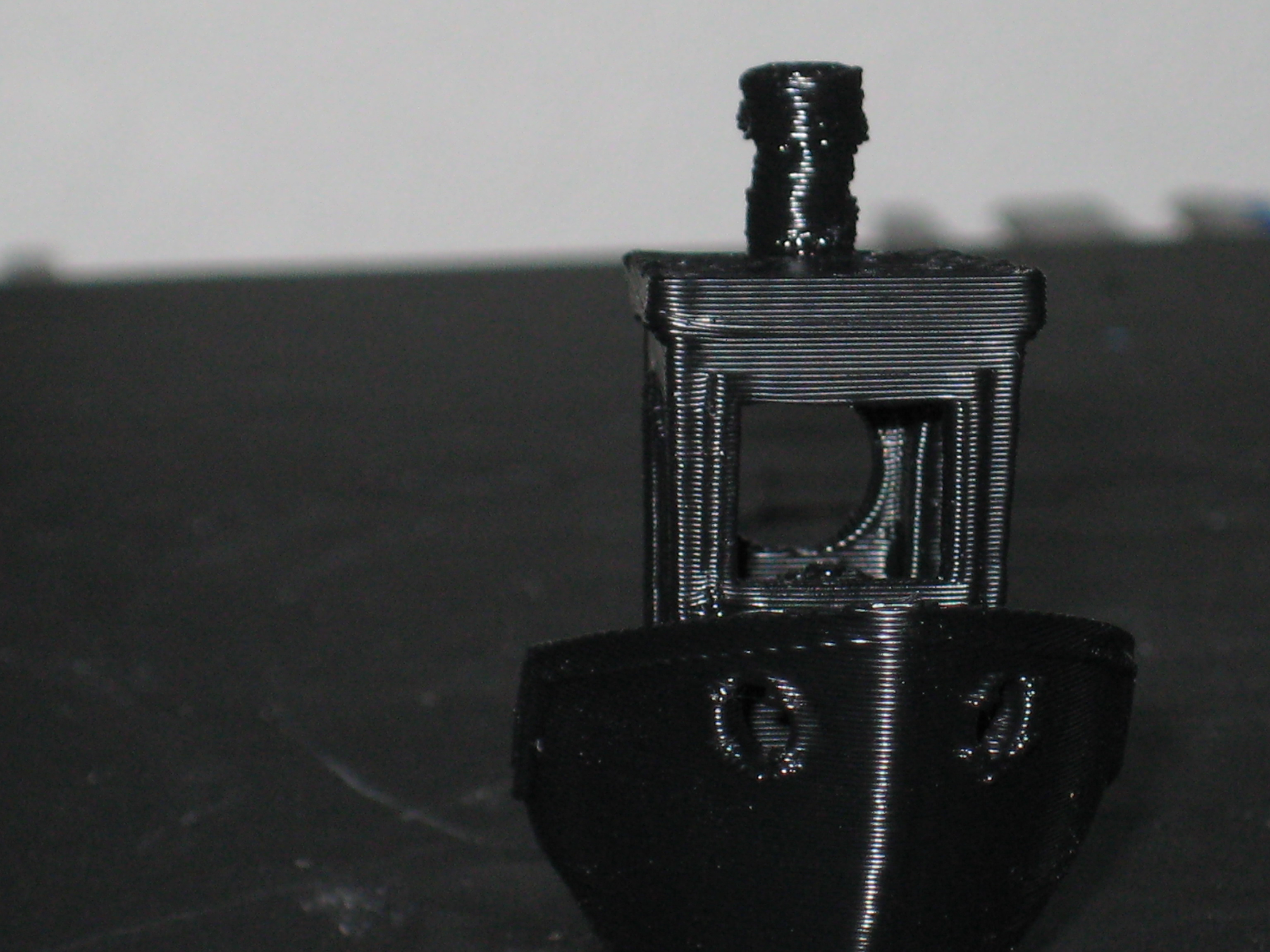


edit: the stack came out a little wonky because the cooling fan is currently inoperative. I’m not sure what causes the occasional artifacts on the back and the sides there. I’m almost thinking that might be fillament moisture?
Regarding hardware requirements, can I get more guidance on the 1/4" threaded spacers and screws?
You don’t say how long the screws should be or what diameter is recommended? I can get 1/4" threaded spacers with any number of different thread sizes, and of course I still don’t know how long the screws need to be regardless.
The screws and spacers can be as long as you want actually, They just need to be long enough to stick out through the holes with a bit extra to allow for movement. Mine happen to be 1/2" long which is probably about the minimum, but I’ve tested with as long as an inch before. The main concern on length with my setup is they can’t be long enough to hit the z axis brace if you are running the openrails Z modification.
The spacer diameter is 1/4". the thread that goes into it is a 1/8" thread. The bolts I am using are wierd metric cap head screws with 1/8" thread, 3/4" long. Any bolt that fits the spacer and doesn’t have a giant head should work though.
The pins are 3/16" pins, 1.5" long. You can make them out of piano wire if you can’t find them locally. This one or a less expensive alternative should work http://www.mcmaster.com/#97395a616/=116mnd5 A 1.75 and a 1.5 would be the best match, but two 1.5’s will work well also.
I just re-uploaded the STL files with all the issues in the model I could find resolved and the corrected bearing holder uploaded. here they are here as well.
Anti_Wobble_Z_nut_mount_top_6_2.stl (119 KB)
Anti_wobble_z_nut_bottom_8_7.stl (188 KB)
Anti_Wobble_Double_Bearing_Holder_2_0.stl (625 KB)
Thanks so much for cleaning the STL’s they look great, and I appreciate your help with the hardware. Just trying to get everything on order so I can do this upgrade in one sitting.
It’s a fine design, and I much appreciate all your hard work.
Thank you, glad you are enjoying it!
Irony, I printed out the 4 nut holders last night, still have to do the bearing holders. And they came out with almost no banding due to z wobble. LOL. That’s like when you bring your car in for service and it starts running perfectly. Of course I’ve had plenty of parts with wobble quite noticeable, so I guess my printer sensed what I was printing and was on its best behavior hehe.
Did the install yesterday. It was a fairly big job because the top bearing on one threaded rod wouldn’t come off. So I had to remove it from the stepper instead.
Did a print and it came out great. Thanks for this great mod.
I had a question, when I reinstalled the x rods I had to pull the printed x rod supports outboard while I tightened the set screws because they wanted to bow inboard from your antiwobble design. And it got me thinking about how far to pull? I could set them at any number of angles. I ended up trying to make them perpendicular to the x rods but after doing that it took out a lot of the travel in your mod (in X). So I think am going to relax them inboard a little.
Other thing was the bearing holder on the right side of the Taz was impinging on the nut holder you designed, so there was barely any travel in Y. I had to cut away at the lower inside flange (for the screw hole) on the double bearing holder. On the left side it had more clearance. Can’t understand why that was the case. Both sides are pretty much supposed the same in that area. odd.
You’re welcome!
The X end plates should be at an exact 90 degrees to the X rods when you are done adjusting, and the anti wobble nut mount itself should be sitting with its main face about 1mm away from the plate on both sides, centered with about 1mm travel available in the Y direction. It shouldn’t be putting any pressure on the rest of the assembly in X or Y, though it may cause a few things to need adjustments as it is a little bit different diameter than the stock pieces. You should only ever need about half a mm worth of travel in X unless you have a horribly bent rod, so you shouldn’t ever need the whole possible wobble span from the spacers. You can measure exactly how much wobble travel you are likely to need by using the depth probe on your vernier calipers. The deepest wobble to the outside surface is the amount of wobble that you would need to compensate for, and that can generally be divided in half since that includes going from one side to the other through the centerline of where the nozzle “should” be if no wobble was present.
The bearing holders have existed in several different version, and there is a chance that one of the versions that has the slightly incorrect feet still exists. How recently did you download the files? The corrected ones should be online now, but I may have missed one of the old files somewhere.
It was the very recent file. I was the one asking for the better quality solid or stl, which you graciously provided.
It could be just a build up of tolerances.
Glad to hear it was supposed to be 90 I figured as much. And it does have about 1mm in X each way so I guess all is well. Wrt the Y axis I just wanted to be sure the foot couldn’t hit. On the one side it was in contact. I just used a razor knife and chamfered the top corner of the bottom innermost flange about 1/8" or so.
I will be taking it all apart again soon to do my X axis 12mm upgrade. I decided to not bother with the shaft in front for now. Will replace the two 10mm x rods and see how that goes.
Just wanted to share this and figured it was a good spot to do so. http://www.thingiverse.com/thing:574550
It seems like a similar idea to what you have done.
I’ve printed out the parts for this and have started piecing them together. When testing the steel pins in the bearings in the lower assembly, they moved back and forth with little effort. However, once I put the upper assembly piece on and stuck the pins through, the parts take a bit more force to move and don’t seem to float very freely. Is this normal? My assumption is that the upper and lower assemblies are rubbing together and that’s causing this issue because this is the only area where the 2 parts are in direct contact. If it’s not intended, I’ll likely just pull the 2 halves apart and do some light sanding.
Edit: Attaching picture
