I just went through over twenty emails with Lulzbot support and we couldn’t figure out what on Earth was wrong with my printer. I’ve got z banding going on that isn’t coming from an unleveled or bound up X carriage, the motor shaft isn’t sheared or broken, all motor wires look fine, the couplers look fine, the threaded rods aren’t bent, my belts are taut, and nothing else on the Rambo looks damaged. The models and slicer don’t have any affect on the banding, good or bad. Here’s a video of what my left motor is doing (that seems to be the culprit but I don’t know for sure now after all the emails): https://www.youtube.com/watch?v=U0tLE2m3qDE. Any community suggestions?
The coupler oscillating as the toolhead moves to different areas of the bed is a normal result of the bed level compensation. There are some noises I can’t identify from that video; it would be helpful to see a wider video showing what movements are occurring when each sound produced.
Can you post a photo of a part that displays the issue? If you print a cube, is the banding the same n all sides?
I had the same, VERY same I must say, problem with my machine. It all happened after I put in the vibe dampener for the Y-axis. Everything was so quiet, I noticed all the different noises that were always there, but not heard. My complaint to Lulzbot was never resolved by them. I did eventually discover what was causing it though. My Z axis motors weren’t in phase, causing the bed to be tilted. The software actually compensates for that by moving the Z as it traverses across X or Y. That’s the shaft movement you show in your video, and what you’re hearing as “ticka-ticka-ticka” at various frequencies that don’t make sense at first.
Your problem is that your Z axis motors are not “in sync” with each other. There are two motors that are given the same drive pulses, but if one stalls and misses/ignores pulses, and the other one moves, they aren’t in time with one another any more. The Lulzbot Mini can compensate for this by creating a virtual plane that the Z motors can “track out” by moving while it prints. However, if your two sides are off far enough, you will hear those thunk-thunk-thunk noises you describe.
While normal to an extent, if your motors are way off, you will probably see and hear a lot more of it.
Please do this:
Do a normal start in Cura.
Note what it displays as it taps all four corners.
Those numbers should be close, within say 0.2mm, and even less is even better.
What are your numbers?? Please post what you have before and after you change it.
Those numbers are what I watch each and every time my Mini initializes before a print. If they’re way off, I abort, figure out why, and retry.
Press the “motors off” button in Cura. With “motors off” you can manually move either Z axis motor/shaft with your fingertips. Try a quarter turn in either direction, make a note of what you did, then re-run the print and note what happens. If the results change in the right direction, continue. Wrong direction, go the other way. Too far, go back a little.
As a side note, it could also be front to back (Y) movement or tilt. If you have that, we’ll figure out how to fix it then.
Here’s what I just ran tonight and it prints pretty evenly with little Z motor movement.

I have the same issues now and will try what you have here. Only problem I am using Cura 2.6.69 and do not have a way of seeing the leveling info taking place. Not that I know of. I liked the Cura that you are displaying here on the forum. Will update here if it helped. Thanks
You can still view that information if you open the “Console” after you start your print/autoleveling sequence. It is right next to your connect and disconnect buttons in Cura.
I also have this problem and haven’t been able to sort it out. I even tried swapping my lead screws to see if the side the problem was on changed. It didn’t. I did find a crack in my motor mount on the side closest to the board. This might be the culprit but damn if I want to remove the board and rewire everything to remove it. Also, this might just be an almost unavoidable consequence of the use of lead screws and something we can’t do much about.
Also try removing the bearings at the top of threaded rod. See if that helps.
I did try removing the bearings at the top. There was no noticeable difference in the banding. I’ve looked at several forums on this subject and, short of replacing the printer, I haven’t seen any one fix this problem.
Old post, I know, but in the hopes someone else with a Mini 1 comes here for an answer regarding the z banding they can read my findings.
I am not a fan of the Mini 2 - the Z gantry is flawed in my opinion (lack of geared stepper, too much lateral forces on stepper, and placement of belts outside the two rods instead of the middle) so I decided to pick up some Mini 1’s for cheap on eBay.
My usual approach when I get a used Lulzbot is to take it completely apart, replace all the metal bearings, reprint all the parts on a tightly calibrated machine, and replace all smooth rods and bearings with hardened steel rods and actual linear bearings. Pro tip: the metal 8mm bearings are typically smaller so you will need reprint the bearing holders and various parts that held the igus bearings with an xy hole compensation of -0.70 (Orca Slicer).
Needless to say, the printer had extremely well-defined 2mm spaced z banding - as expected. I tried dozens of things to fix it, but what ended up eliminating it was a combination of things.
- Removed the top two z axis bearings. This is not terribly hard - you can remove the top plate of the case and access from the top.
- Reprint the top z mounts with an xy hole compensation of -0.20. This is important so the z rods are rigidly held.
- Remove all binding in the system from the stepper mounting and the z nuts. This is easily done by loosening the four stepper bolts and three z nut bolts on both sides. Run some gcode that moves the gantry up and down like 50 times. It will reach an equilibrium where the steppers will stop wobbling and the z axis screw will turn straight (not wobble in the now empty spot where the top bearings used to be). Screw down all loose screws, carefully so you don’t throw it out of alignment.
The z screws are now tuning forks, in a sense, so expect a little bit of noise when the gantry is moving at full speed up or down. That’s fine as this is only during homing. But you can sleep well knowing the banding is now gone. There’s still some “chaos” in the z, but it’s not that annoying 2mm banding that you just can’t unsee. Just your typical bed-slinger-with-a-heavy-gantry type layer stacking that all printers have.

1 Like
I had to take this even further, because I found the specific reasons these printers have this issue.
I present you this:
Look at the measurement, or more specifically, the tolerance of the part that clamps to the coupler. They list it as 5.00mm with a minus tolerance of 0.2mm. I measured mine, and they definitely where in that range. But the issue is eccentricity of the entire rod within the mount as it turns. When you constrain the rod at the top and bottom any eccentricity will have dramatic effects on the prints. You could get lucky, your coupler end might be exactly 5.00mm, or you could get something less than and that is where the issue starts.
Removing the top bearings is a half way solution - as you can still see some banding but it’s mostly gone.
After messing with this printer for weeks now, the total solution involves replacing the couplers with similar but beefier varieties. I used these:
Next you have to completely remove the bearings in the Z axis - ALL FOUR of them. This means the weight of the gantry will now rest on the couplers. And it’s not trivial at all to take the printer apart to the level needed to do this, but it’s necessary.
I thought about replacing the z steppers with ones like on the Prusa I3/I4 but that rapidly got too expensive, so I instead opted to try to reuse the screws as best I could, despite the tolerance issues. Allowing it to eccentrically move without the bearings imparting that motion to the print will enable the super nuts to take up the slack, so to speak.
Here is a final after print:

It’s not perfect, nothing is unless the lead screws are replaced, but it’s miles ahead of this:

For extra giggles, this is how the printer was printing the day I got it, and how it’s printing now. The igus bearings were so shot I can only imagine this thing was printing every day for a decade.

This was a trashed eBay find that the seller didn’t think even worked. Now it’s one of my favorite printers. It’s a testament to Lulzbot that not only was I able to get detailed documentation and printed part STLs for printer, but that forums like this can get a printer from 2016 printing like any modern printer.
1 Like
Hi there, I just created an account to say thank you! I have two (3rd gen) mini 1s, and it was definitely doing some form of this z-banding.
I did most of your fix to one of them and this is the result:
(I didn’t reprint any of the original printer’s parts, just removed the bearings and installed new couplers)
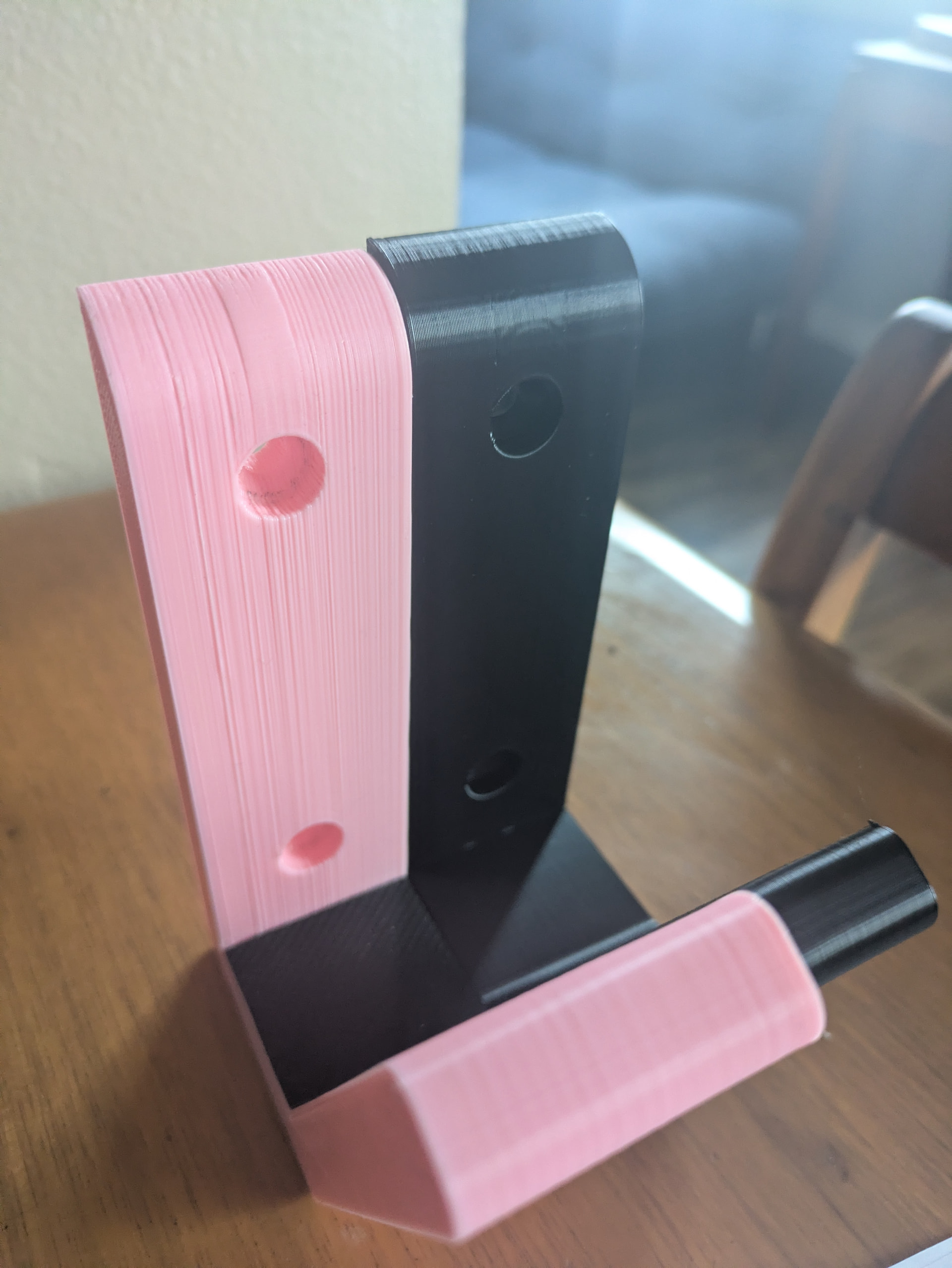
They are slightly different parts, and I sanded the pink one to make it smoother, but you can see the black print is silky smooth comparatively.
I will warn people who might try this - the set screws in the original couplers on my machines had/have red loctite on them so they are not easy to remove and replace - I had to cut/drill them out. I’m holding off on doing the second printer because it doesn’t have the same issue at the moment.
Thanks again @zenotek - I can confirm your solution above by works!
Another thing I will note after doing @zenotek ‘s modification is that when the gantry moves down the screw at the start of a print it definitely makes noise now. It doesn’t affect the operation of the printer. I’ve printed several prints with this mod, and they all have come out perfect. It does not make the noise when the gantry is moving up or printing.
If anyone knows how to mitigate the noise without affecting the print quality that would be really cool.
Without the bearings, fast z motions (only when homing) hit that resonance frequency but won’t happen during printing. I Klipper’d mine and slowed down the z homing speed so it’s not as bad.
Qidi printers have these plastic caps they stick on the z rod ends so they are constrained a tiny bit - finding one of those and sticking it on the z rod ends would probably absorb most of the resonance. You could model one quickly in Fusion and print it in petg or something “chewy” and springy - TPU would be no good since it would impart too much friction.