Well, it’s just about finally done. Got one more backplate to print, then I can start attaching things. Mock up seems to indicate everything will fit fine.
The micrometer based Z axis. I’m actually kind of surprised I haven’t seen one like this aside from the entirely made of extruded plastic ones on thingiverse so far. Maybe there’s a reason. if so, I’ll find out!
I also replaced the Angle brackets. I’ll polish them up nicely later. You can also see my top secret project “lulzbot AO-10x feet made out of washers and rubber cap things and screws and some t-slot nuts that may or may not work” in there. Probably need an acronym for that project heh.
Next up should be fitting. I’ll start with the Idler side, and assuming it lines up, then the X motor side. It will be a bit of a pain since I’ll need to dismount the Z motors and uncable them, so I probably won’t get a chance to finish this aspect of things until this weekend. I may get the deck plates on before then. we’ll see.
Made a project page for this on Thingiverse since the parts are all done. Will upload the final fitting pictures once they are done. http://www.thingiverse.com/thing:220959
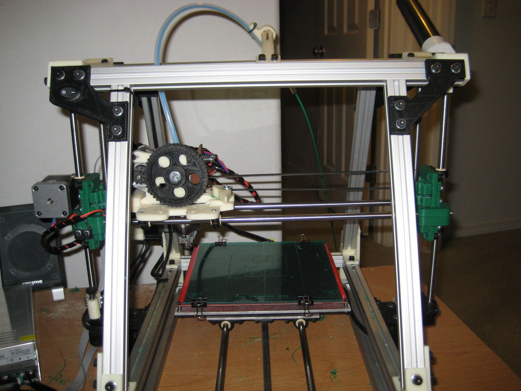
Well, Here’s half the final assembly anyways. My plan is to run a few prints through it in hybrid mode and see how it looks before I add the X motor side this weekend. So far the whole thing fits like a glove. I had to add longer screws to anchor the upper spar mount plates to the top gantry side plates, but aside from that I couldn’t have asked for a better fit. Also top secret project Mendelfeet was also a success apparently. I’ve been running the Z axis up and down the gantry for the last few minutes, and it moves smoooooth!!!
The entire frame is much more solid than the admittedly already really solidness it had before. Once I get the other side on, I’m pretty sure I could park a car on top of this thing and it wouldn’t notice. The angle brackets and extrusions on the bottom really are overkill. But that back spar and rail is never going to accidentally move even slightly, so I’m ok with it. This modification also gives the frame enough stiffness that you could probably use it for a light duty cnc wood router with decent results.
It’s all part of my secret evil plot to fill up your forum server! Mwahahahahahah!!
heh, you’re welcome! I hope other people will actually make a few of these parts in the future, so I want to make sure people can visualise where everything goes easily. Plus it gives people a chance to critique my prints and designs whcih can be helpful. I’v
Printing with the half rail on right now. So far everything looks good. Humidity is super high at the moment so i’m getting some humidity related print defects, but everything is lined up just fine.
One thing odd I noticed. By putting my printer on the little rubber feet I made for it, it has literally cut the noise it makes in half. I thought I was going deaf at first. but apperently that solid frame was using the top of my print table like a resonating chamber and amplifying all the noise. It’s almost too quiet now.
other side is on now. Can’t test print anything though because I A. ran out of filliament and the new shipment isn’t getting here until tomorrow, and B. I managed to break the z endstop off and need to re-soldier it, only problem being I apparently don’t have any soldier in the house. So, that will get fixed tomorrow.
Assuming I don’t encounter any issues everything looks good. Will put some test prints up when I get the motor side dialed in. Then its on to finish the top deck plate project!
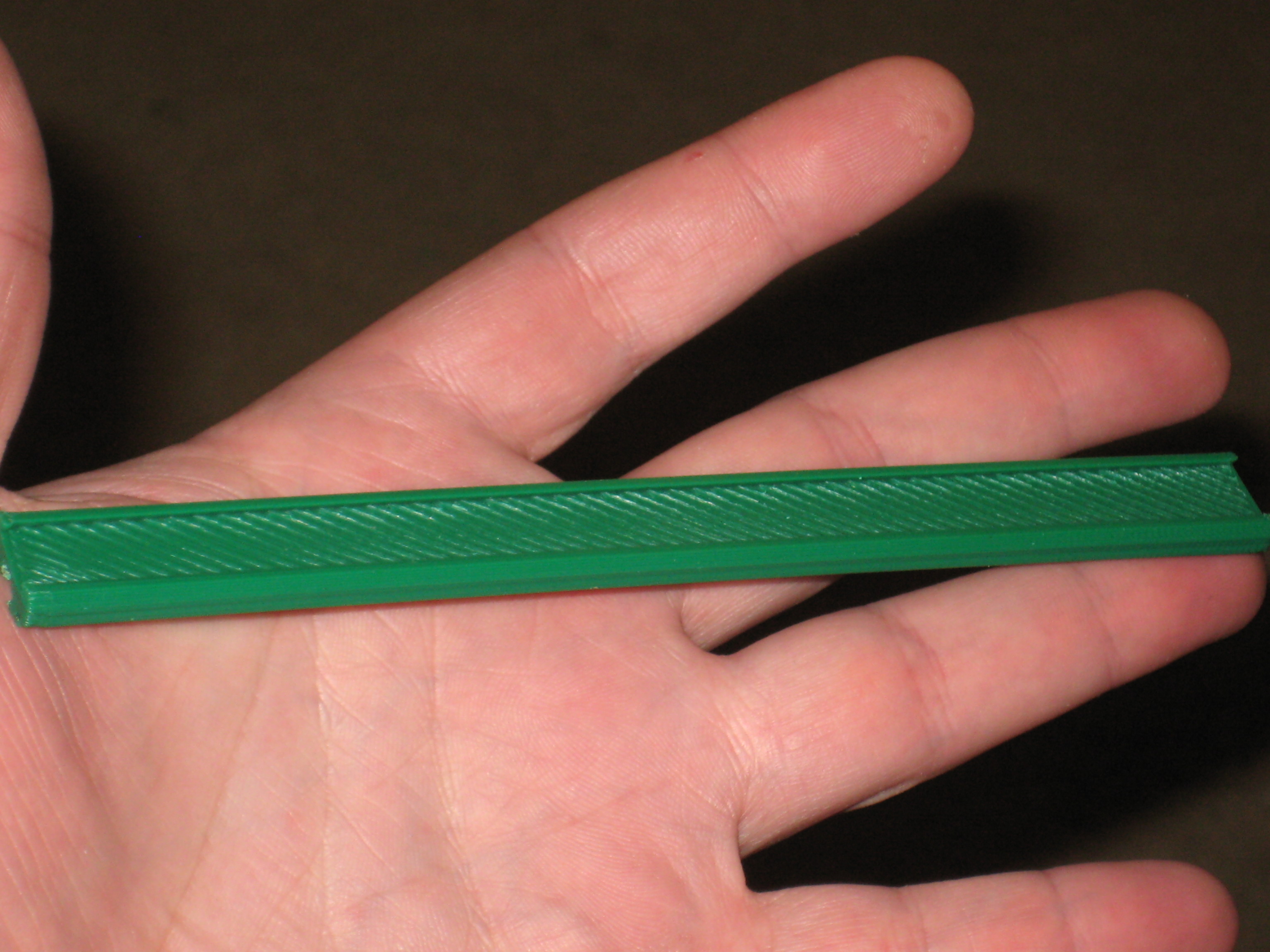
First prints with both ends on show promise. I do have a little tuning left to do on the idler side. Nothing too exciting, just some simple flat LED holders, but I think it’s pretty good quality for a .5 nozzle in a fairly small part I’ll be printing some more stuff with flatter walls later in the week which will tell me if it was a big improvement there.
Nothing particularly entertaining there but it does show how it is printing
Edit: By the way, the micrometer based height adjuster? Best idea in the history of ever! I get really really fine layer adjustment, and the damned thing stays exactly where I set it!!! the other one would tend to drift slightly over time. I’ll make a rod based version of that so people can experience the awesomeness at some point in here.
Yeah, I think I have some before pictures somewhere around. I’ll post some later tonight. Basically that printer started out life as a bone stock AO-100. Then it got widened and the carriage swapped for a quick fit unit, along with the 60mm height increase parts and the RAMPS cover. After that, the AO-taz modification got designed and installed. I tried installing a LCD at that point but it kept beeping at me so thats been on hold. Then the mendelmax 1.5+ rail modification went in using the Trinitylabs rail. From there the Linear Z rail parts and new couplers were added. It’s a bunch of work, but done over time slowly it isn’t too bad. I’m not sure it’s an AO-100 anymore though heh.
More modifications are in process or planned too. The top deckplates being the next one up, along with the lighting and electrical modifications. Also the new quickfit carriage with fan and Z probe mount spot is mostly done. The belted extruder will go on soon too.
Once those are all in place, about the only thing left to do will be potentially a gantry modification, and X rails of some sort. I don’t really like the offset X rails of the mendelmax 2, and i’m not sure the stacked TAZ rod arrangement would be best for a rail based path, and putting 2 20mm extrusions on either side of the extruder is going to take a bunch of usable space, so I don’t know where i’ll end up going with that part.
I’m kind of halfway considering making upgrade kits to sell, but the logistics of that all would be somewhat complex
The Y rail went in after the AO-Taz pieces went on but before the Z rails. I don’t seem to have a good picture of the machine at that point though.
The only original pieces that are in their original locations are the 4 side extrusions, the 4 gantry members, the RAMPS backplate, and the 4 black gantry corner support brackets. And most of the electronics and bolts too I suppose.
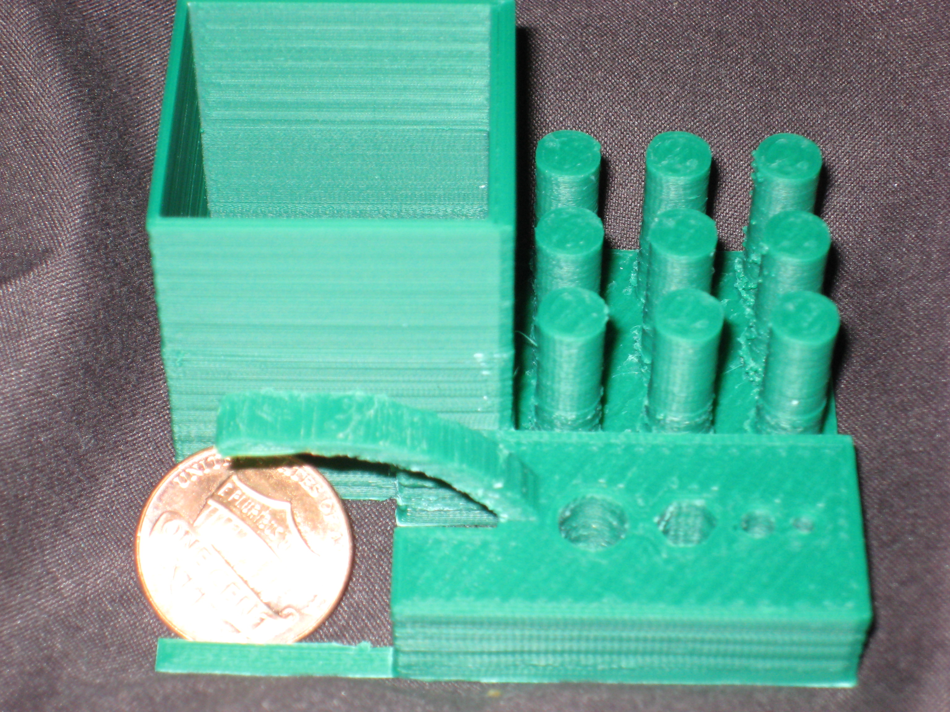
Here’s my first serious attempt at printing something very high quality with this modification. As you can see, there is room for some additional tuning, but it’s not bad for an old AO-100. I do apparently have a slightly bent threaded rod which isn’t helping, but I think the rest of the banding is actually in the carriage and the 8mm carriage rails rather than in the Z movement. I’ll work on them next. The green actually makes the banding look worse than it is though too.
Edit: for clarification this was printed at 0.10 mm layer height. at normal heights the banding is now invisible.
Piercet,
Those parts are looking really good! The corners on that box look really sharp and those cylinders tooI am amazed how fast I are pumping out these upgrades! Thank younger the pictures.
Do u know what cause those little bubbles at the ends on the prints? (Gantry photos)
Thanks! I’ve got a few more upgrades in progress that haven’t been officially called projects yet aside from the still in progress deckplate modifications (a new quickfit stabilized X carriage based of BAM’s, A fully supported 300mm ballscrew for the Linear rail Z, A Linear slide (or maybe Rail) Horizontal X axis modification different than the Mendalmax 2.0 setup, and possibly fiberglass sideplates for the gantry to get more of a finished “office product” type look for the printer. amongst others). Should be enough to keep people entertained for a few months anyways. at which point maybe i’ll have a printer upgrade kit for sale or something along those lines?
The Bubbles are the result of a few things. Humidity and moisture content of the filliament is a big cause, along with overextrusion. FOr the moisture issue, filliament if you look at it under a microscope is basically a very tiny sponge. Holes in the plastic from the extrusion process to make the filliament in the first place collect tiny amounts of water, that turn into steam when they hit the hot end, which causes extra plastic to extrude
Extruder calibration is the other big culprit. Especially printing at micro layers. Basically if your filliament isn’t exactly measured, and your extruder isn’t dialed in to the point where extruding 10mm of filliament will result in exactly 10mm of filliament travel, you can get bumps in the corners or on circles.
The other source of the bumps is a slicer bug that is fixed in version 1.0x, Basically filliament extrusion is like pavement on a road. There is less filliament needed on the inside portion of a round hole, just like there is less pavement needed on the inside lane of an oval race track. THe older version of slicer didn’t take that into account as well as it could have, which is now fixed in the latest version.
Beyond that, temperature and humidity issues can also account for unexpected bubbles. Short of an isolated climate controlled dehumidified environment, they are difficult to remove entirely in my experiance so far. Storing unused spools of filliament with dehumidification sillicon packets seems to help somewhat unless you live in an area that is pretty much 100% saturated year round like Ridgefield.
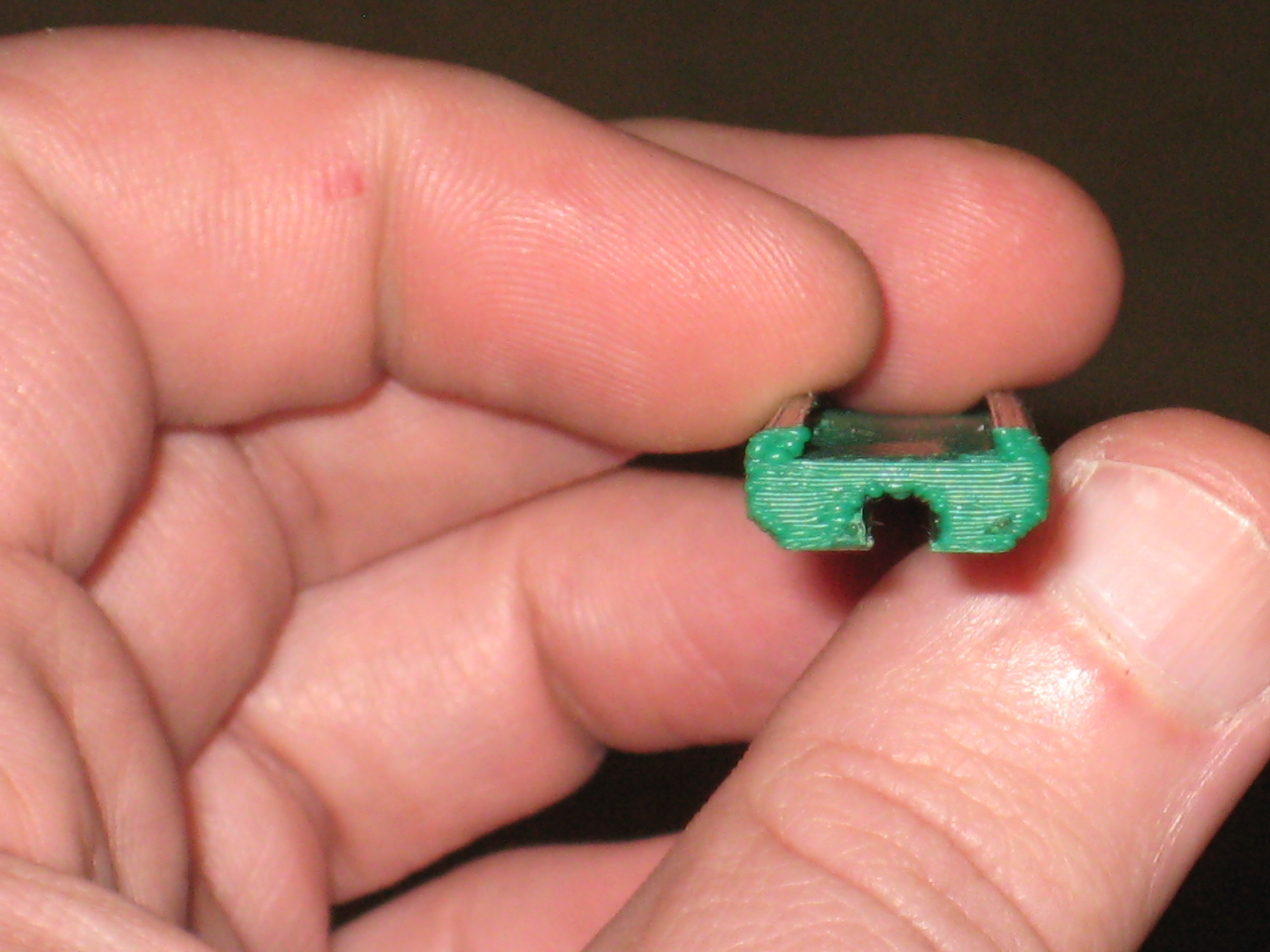
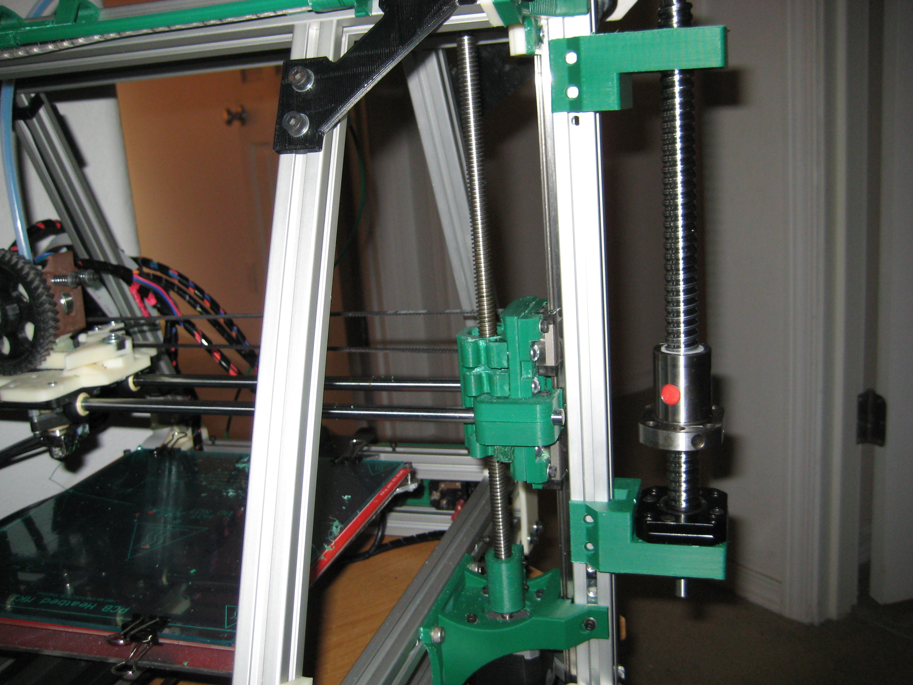
The top bracket isn’t anywhere near the final design, and the whole assembly will replace the existing acme rod on the inside. The TAZ style spring will be replaced with a fixed adaptor, hopefully reusing the existing clamp ends for now. I would have preferred that the mounting flange was on the other side, but repacking the balls in one of those is amongst the most annoying chores ever invented, so i’ll probably work around it. Not bad for a $30 ballscrew though so far. Still need a top support bearing, as well as a design for the nut retainer. I’ll also end up rebuilding or at least relocating the z height adjustment screw assembly since it will be in the way of the lower bearing bracket. No idea where that will go yet though. This one is going to take a bit to get right. and then there is the whole leadscrew e-steps issue. I will say this, the new one moves a hell of a lot smoother than the existing one for certain.