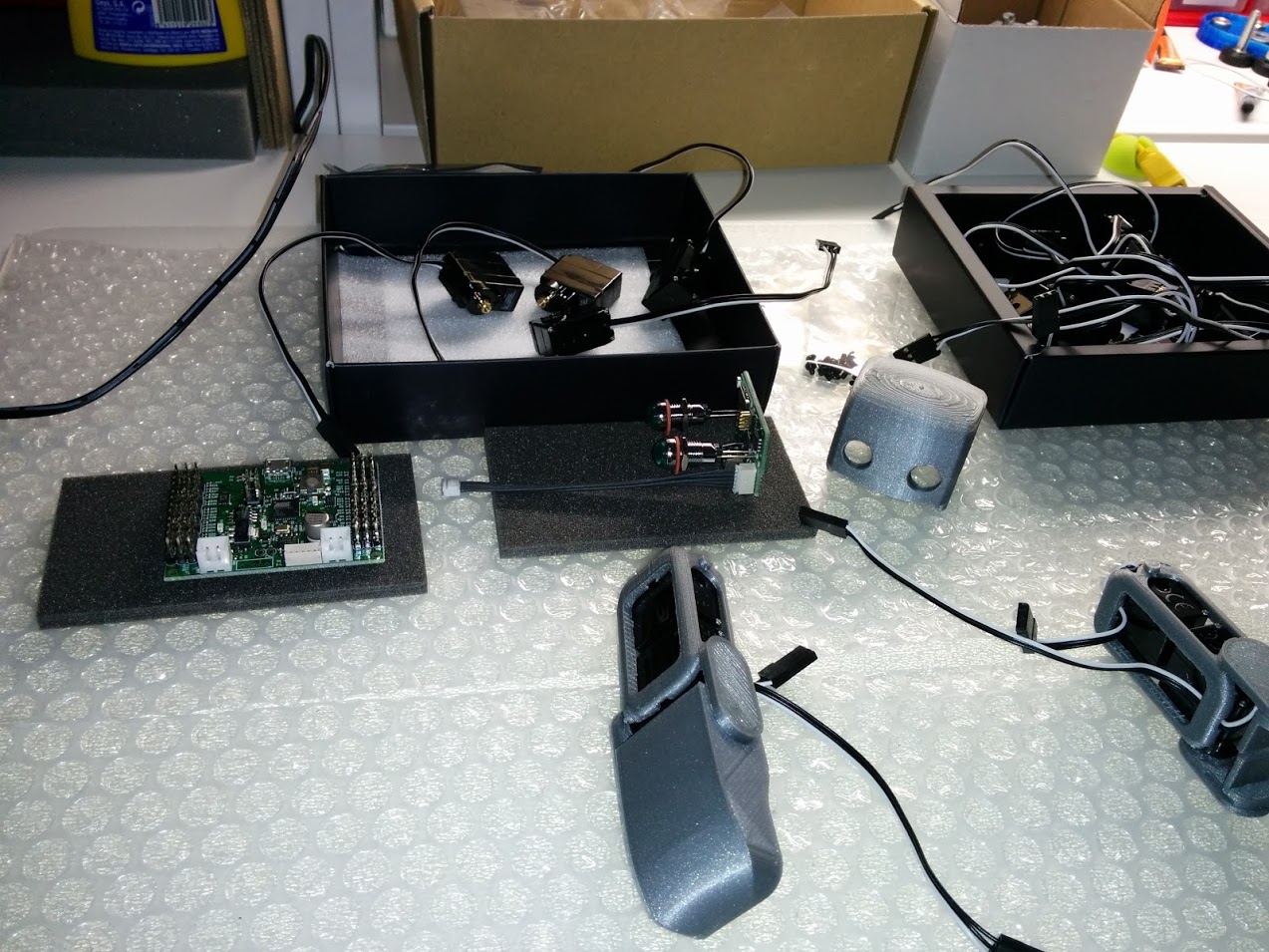
Hi! I´m trying to print a PLEN2 robot chasis, using a normal ESUN silver PLA filament.
I managed to get some parts “correctly” printed (no perfect), but I´m having a nightmare with 70% of the rest.
I´m still not a pro with my TAZ5, and even worse there is practically no updated documentation about this robot or is poor.
Here are some thoughts until now (5 days printing low-quality parts).
Fitting parts: not even once
There are this small gears (about 1cm) that must fit an area of exactly the same size. There is no gap at all. 1cm piece for a 1cm hole.
http://plen.jp/playground/wiki/_media/specifications/print_detail/servo_horn_rev1.stl.placement.png
http://plen.jp/playground/wiki/_media/specifications/print_detail/servo_bracket_type1.stl.placement.png
- I first tried lowering the external shell width (from 1mm to 0.5, having a 0.5 nozzle). This made some improvements, but still I had to “operate” with cutting and sanding tools to make things fit. I suposse that setting the shell to 0mm is not an option, right…?
- I noticed that the first layer was too wide, making some parts hard to fit, so I tried lowering the default bottom/top thickness from 1mm to 0.25, but pieces were not well fixed to the bed this way, so I returned to 1mm.
- After a long research (and following valuable advices in a previous post) I was 99% sure that this was a case of E-steps settings. So I dug into it and tried to measure the length of a 5cm extrusion step (with quite primitive tools…) and I didn´t see any noticeable gap. Also, many people asures that the default factory settings for the TAZ5 are quite accurate. So could e-steppers really be a problem in this fitting pieces case? Or I´m looking on the wrong direction? Anyway I will try to make a more exhaustive measure on this to make it sure.
- When support material is required, this holes where the other part should fit are always filled with garbage very difficult to remove, making fits even harder.
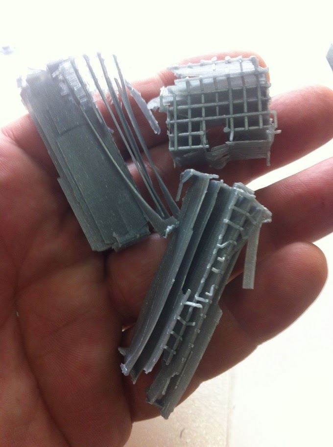
My pieces are not solid enough
Well, this is evident: I broke 90% of all the small tabs that should have made a secured “click” when trying to fit them together.
I read that small parts should never be 100% solid, I was using a simple 10-20%. But it seems that this (even being a very slow value itself) is not applied proportionally to the size of the piece itself: 20% is the same separation between infill walls when printing a 3cm figure than when printing a 30cm one, is this concept right? Could a 80% be right in this case?


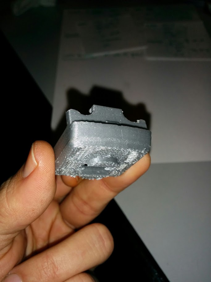
I officially hate to use support material
Seriously, I´m angry with myself for still not mastering this important setting. I always have a lot of problems to print some pieces when they need support. I´m now using a custom setting in my last tests (X/Y distance 1mm, Z distance 0.15), but it seems I´m going backwards… My hand is literally destroyed for spending so much time removing this hard-as-rock support material. I´m getting something wrong and I need help with this, no doubt.
(In the previous picture you can also see that I couldn´t remove all the support material, impossible)
Also, if a layer has to be printed “on the air” using support material, the final result is not smooth at all.
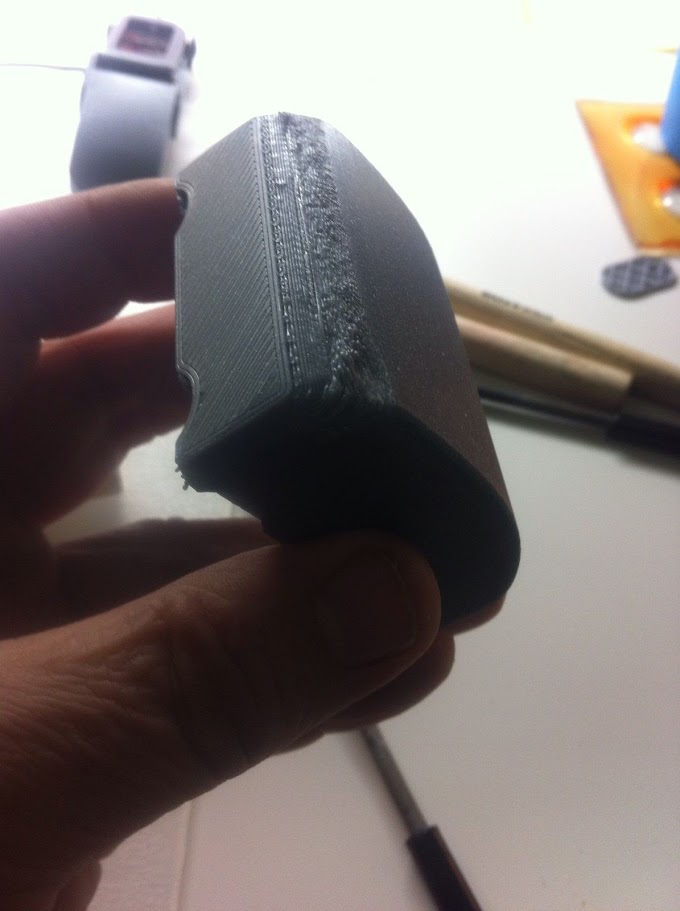
Curved parts have bad resolution
This is really weird. When a part starts drawing a curved structure from the bottom, every single piece I printed showed this problem. If the curve is somewhere at the top, it is perfectly printed. As a clue, I noticed that when looking this first layers being printed, they seem to slightly elevate itselfs upwards, maybe because the hot of the bed being so close or the layers so thin? (0.15mm height). When the nozzle came to that areas, the pression of the extrusion would push the layers to its proper position, and with consecutive layers, the weight itself slowly makes the problem to dissappear, but that first layers… Awful!
 Could this be also a fan-related setting issue?
(You can also notice it on the previous picture, the first layers of the head part)
Sorry for posting so much comments at once, feel free to add your opinions/thoughts to any of them.