Replaced 1.1b board with 1.3a + LCD -- Mystery Wire?

OK,
I have a very old Gen 1 of the Mini, the miniRambo Board was a 1.1b board, and I wanted to add the LCD kit so got a 1.3a board.

I carefully swapped the wiring also compairing it to the Lulzbot wiring diagram. Got the LCD installed, flashed the firmware, and everything was looking good.

The wierd thing was that my printer seemed to have an extra undocumented wire pair. It was black and blue with a 2 wire connector on the end and was attached on my 1.1b on the first set of 3 jumper pins just above the ZMax connection point. I can find no documentation what so ever for what that pin set does or why there was something attached to it.

However after I accidentally crashed by print head into the bed while messing arround with the LCD controller, my printer froze and failed all other communication attempts until I removed the wire. Then everything started working again, and printing is working just fine, and I am super happy have that LCD control. Just being able to easily adjust the z-offset is heaven and being able to easily remove filament etc without going through Cura is awesome.

So does anyone know that that mystery wire is for? was it a failsafe for crashing the head into bed? But then why would the printer become un-usable after that happened? I haven’t tried re-connecting the wire since. And prints are fine, but I worry that I am missing something by just leaving that wire hanging. All other wires in the wiring diagram are attached so this is clearly an undocumented extra wire. No idea what it is actually attached to in the printer.

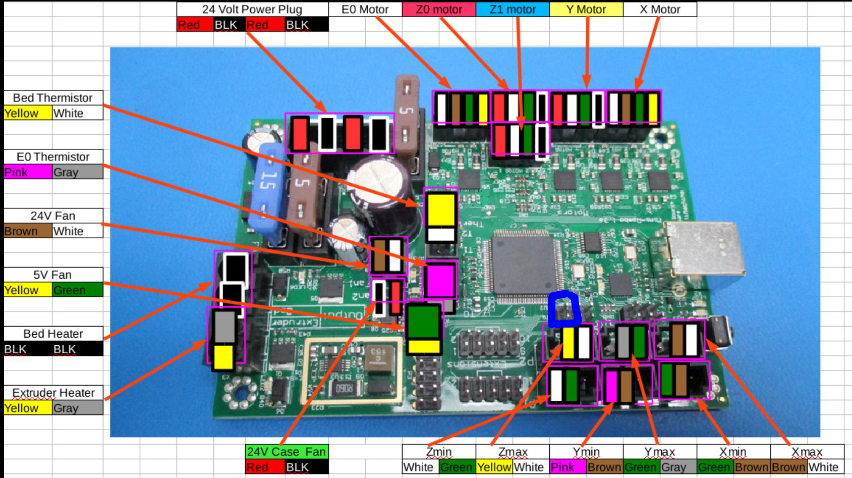
Picture of the pins it was wired to is attached, I drew a blue box around the pin in question just above the ZMax

I believe there’s a limit switch that’s no longer used on the new rambos. It might be the x since it’s now on the extruder

I’ll double check.

Yes, I saw in another thread that this is the z-min switch since the z-min switch is actually used to power the extruder sensor to auto-level the bed. The wire is definitely acting like the wires go to a limit switch, as it did trip and stop the downward motion when it hit the bed (by crashing the board!), My guess is lulzbot is probably no longer programming the ICSP chip correctly on the board to do what they intended as a limit switch override. The only reason you should get into a z-min situation is like me where you are either moving to head manually, or adjusting your z-offset and screw up (both of which I have done.). Would be nice if worked correctly as an end stop (stopped the downward movement without crashing the board) for potential accidents but probably non-essential to actually printing.

Here was the thread that confirmed the mystery wiring… looks like it may not be compatible with current min Rambo boards: Installing a new mini Rambo, questions?
Doh… maybe the old limit switch does work, looks like I installed it wrong when I swapped out the board. There is a good picture on the thread here: Z-axis Bed Probing not working
Of how it is suppose to be wired, I had it rotated 90 degrees so on the wrong pins hence probably why it crashed the board…

Yes, I found some info on the forums, it is z-min limit switch that is no longer supported. No need to continue to investigate, everything is working.

Bret

did this make the steppers quieter as well?