Tight fit with LulzBot TAZ 6

I printed a robotic part to hold a servo, joining 2 links of the arm.

I ended up with a too tight fit, cracking the part once I insert the servo.


In other parts, it won’t even slide in.

What could have caused this problem?

Ideas I am planning to explore to fix it:

  • Reduce layer height. For 0.5 mm nozzle, planning to set layer height = 0.3mm. I had 0.425 mm. The dimensions will be more precise.
  • If it is an over-extrusion problem
    • assuming temperature was too high, lower it from 230 C down to 190 C
    • reduce flow rate to print less material, lowering from 1 down to 0.98

Ideas I’d like to avoid

  • Scale parts by 1% to readjust the actual printed size
  • Reduce print speed for more accuracy

Everything?

Improperly designed parts for the material.
Bad measurements of the parts.
Insufficient clearance between parts.
Incorrect tolerances.
Poorly calibrated machine.
Improper extrusion calibration.
Warping.

Start with the basics and printing test objects to determine the tolerances of your machine, and build that into the clearances between your parts. If the part is warping during print, address that.

I’ve used the “Horizontal Expansion” setting to slightly increase opening sizes without adjusting the scaling. Typically something like -0.1

1 Like

Thanks for suggesting this workaround. I’d rather avoid expanding the holes. I’d like to figure out why the 3d-printed part has dimension inaccuracies compared to the model.

The part has a pretty tight fit, requiring the actual part dimensions to be very accurate.

It turns out that some rounded corners are causing the problem. They show on the external wall. Those protuberances in the inner hole block the servo from sliding in.

When i switch from 1 layer thickness to 2 layer thickness for the shell, i start seeing drooling at the 90 degree angles. Adding the 2nd layer just exacerbates the rounded corner issue.

Adding 1 2nd layer in the shell fixes the visual effects we see with single layer thickness. It also increases sturdiness. But it introduces the no fit issue due to those rounded corners.


Settings:

  • Filament: PLA Pro
  • Nozzle Temperature: 220 C
  • Bed Temperature: 60 C
  • Nozzle size: 0.5 mm
  • Layer height: 0.425 mm
  • Infill: 13 %
  • Top/Bottom Layer Count: 1
  • Shell Layer Count: 1

The part has visual defects where the top layer falls in the holes where there is no support from the infill. Also the lines on the vertical wall don’t superpose nicely.
Changing Shell Layer count to 2 makes the part look great except the servo no longer fit.

Flowing plastic can’t make a corner.

If you need to put something that is truly square, try designing with a small opening at the corner.

1 Like

This is the same problem I have with the Seeed SO_Arm100 kit. I tried various settings on the stepper motor gauge, but haven’t found anything to work, yet. I am not going to start printing the whole arm until I can get the motor to fit into the gauge correctly.

Seeed provided STL files with Ender and Prusa labels, but neither would fit when printed on either of my Taz6’s. One Taz6 has an SE 0.50mm tool head and the other has 0.5mm tool head I got off eBay for 1.75 filament.

I haven’t had a chance to work with this lately.

I sent a message to Seeed asking for the CAD files because editing STL files is such a pain in the ass. I haven’t heard anything back from them.

When I get a chance to play with it again, I will try the Horizontal Expansion setting, because I do not want to try scaling parts and cause other issues in trying to get the arm to fit together.

The message I sent to seeed on January 17th


is below:

seeed SO-ARM100 Pro Robot Arm STL Files

I purchased a kit to build a robotic arm from seeed. The kit uses downloaded STL files so one can print the arm parts. They provide STL files for Prusa and Ender printers. They also provide a guide to be printed to determine how accurate the prints will be.

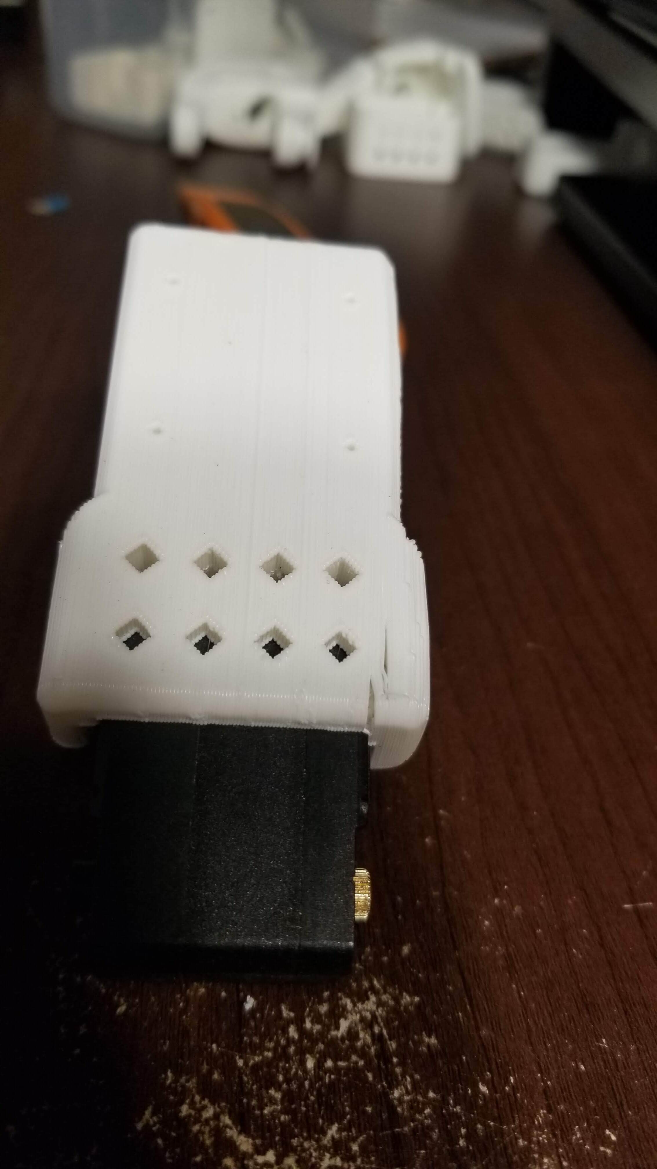
The guide is a rectangular block with outsets at each end. It is designed to accept the STS3215 stepper motors used in the robot. The idea is to ensure that the stepper motors fit tight in the arm parts.

I printed the guide on two Taz 6’s, one with a SE 0.50mm toolhead and one with a made to order replacement toolhead designed for 1.75mm filament. This toolhead has the same 0.50mm nozzle as the original toolhead. (LulzBot TAZ 6 1.75mm Single Extruder Tool Head .5mm Nozzle, plug and play | eBay)

I used Cura 4.10.13 Experimental to slice the guides in High Detail for both printers. The 1.75 printer was using Tough PLA from Inland and the SE printer used Polymaker PolyLite PLA.

The prints from both printers are too tight to get the stepper motors inserted. The specs on the motors say 24.7mm by 35mm. Using a digital caliper, I measure the printed guide as having 24.49mm and 34.68mm inside measurements. When I load the STL file into my CAD program, the long dimension seems to be .1mm shorter than the stepper motor specification (35mm). And, narrow dimension is exactly 27mm, which is the motor specification. These dimensions leave absolutely no room for filament contraction upon printing.

Has anyone tried printing this robot arm on a Lulzbot Taz 6 3D printer?

Are the CAD drawing files available for download so I can adjust them for a LulzBot printer?

Thank you for your assistance with this.

For the outwards corner, a fillet can smooth a sharp angle. Rather than editing the CAD files, it is preferable to calibrate the printer settings to mitigate the bulging.

The combination of those 2 parameters caused the issue for me:

  • layer height = 0.425 mm
  • shell thickness = 0.850 mm

What are your 2 settings for the 0.5 mm nozzle ?

It turns out that reducing layer height also fixes the issue:

  • layer height = 0.35 mm
  • shell thickness = 0.70 mm

Layer height should not be set too low otherwise the nozzle won’t extrude during the 1st layer.

Overall, reducing the layer height improves the quality of 90-degree corners by allowing finer details, reducing overhang, improving cooling, and providing better control over material deposition.

I believe that both the Prusa and the Ender printers have 0.4mm nozzles. The TAZ 6 has a .5mm nozzle. With the tight tolerance you are working with, this difference could be part of the issue.

I had a mechanical failure on 1 part. I reprinted it with following settings which should improve its resilience.

I ran into the rounded corners issue again as the servo would no longer fit in the tight fit.

The maker space staff recommended smoothing them out with a metal lime, square preferably for corners, but rounded one works too.

For 1-off project, this will also fix your issue right away.

Thanks for the help on this. I reduced the layer and wall thickness and set the Horizontal Expansion setting to -0.1 on the Taz6 with the 1.75 hot end. The test gauge I printed slid over the stepper motor with a nice fit.

Now, onto the print of the robot arm. :slight_smile: