Hi ! At this moment I fried almost all my endstop pins. I have only xmin and ymin. To avoid buying an other Rambo board, I’m trying to use a mcp23017. The hardware is allways working and tested with a basic example : blink.
I want Marlin read the state of pin 0 on the mcp23017 and not the pin 10 of the atmega. Can someone help me to adapt the Marlin firmware ?
This is what I’ve already done : hardware part
mcp23017 connected to I2C.
a pushbutton
a pull-up resistor
Marlin modification
I add Adafruit_MCP23017.h/.cpp into Marlin directory then I changed the file Marlin_main.cpp to add
The main point is I change READ(Z_MIN_PIN) by mcp.digitalRead(Z_MIN_PIN). Now the M119 change when the button is pressed. But this is for information and will never stop the printer. I guess I’ve to change the stepper.cpp but nothing happens when I modify it.
But this is for information and will never stop the printer
Triggering endstops should not stop the printer unless ABORT_ON_ENDSTOP_HIT_FEATURE_ENABLED is defined. What are you expecting to happen?
I guess I’ve to change the stepper.cpp but nothing happens when I modify it.
It seems like you’re saying the endstop flags aren’t being triggered in Marlin. It also seems you have only changed how the pin is read in the case 119 statement, you will have to perform mcp.digitalRead(0) everywhere that READ(Z_MIN_PIN) is being performed.
In your pins.h header file try setting Z_MIN_PIN to 0; you will need to use mcp.digitalRead(Z_MIN_PIN) instead of READ(Z_MIN_PIN) and see if that does it. Make sure to replace any other preprocessor calls using Z_MIN_PIN with the corresponding functions form the Adafruit_MCP23017 library.
Or try explicitly replace each instance of READ(Z_MIN_PIN) with mcp.digitalRead(0) everywhere like this:
I see you said you are using a RAMBo, you must not be using the reprap discount full graphic smart controller since it occupies SDA (arduino pin D20) and SCL (arduino pin D21). Do you have multiple devices on your I2C bus? If you are only using I2C for your mcp23017 then you have the option of simply using D20 and D21 as your endstop inputs (set with internal 10k pullup). Do you need the extra pins provided by the mcp23017? I’m assuming you still have available pins on the EXT 2 auxiliary of the RAMBo, unless they’re all occupied or also destroyed, why not use any of those for your endstops… ?
Hi ! Sorry for the very long delay but I thought I would have received an email if someone had answered my question.
Thanks for your help. So I can’t test now maybe in the week-end, but I can answer some of your questions.
So are you saying the endstop is being triggered? …Triggering endstops should not stop the printer unless ABORT_ON_ENDSTOP_HIT_FEATURE_ENABLED is defined. …It also seems you have only changed how the pin is read in the case 119 statement
Yes, I knew all this, sorry if my previous comment was not clear about that. To summarise this is how I did
(I’m not familiar with C and Marlin so I worked step by step. )
First step : be sure that I can use the mcp with a very simple example. (This was OK)
The second was to have the M119 statement reading the mcp pins. (OK too, when I press an endstop I get it triggered)
and the last was to replace all READ(Z_MIN_PIN) with mcp.digitalRead(0)
The last step is more complicated. In fact, with mcp.digitalRead(Z_MIN_PIN) instead of READ(Z_MIN_PIN), the motor does not move in Z axis when the hot head homes.
you must not be using the reprap discount full graphic smart controller since it occupies SDA
No, I’m using the full graphic smart controller. Are you saying that I can’t add another devices when I use it ?
I’m assuming you still have available pins on the EXT 2 auxiliary of the RAMBo
If you speak about all the MAX endstops, I destroyed all of them and I did not find any document that describes
the extra pins (arduino pin number).
If you’ve properly replaced each instance of READ(Z_MIN_PIN) with mcp.digitalRead(Z_MIN_PIN) then using M119 should show the state of the switch actually change when you depress and release the switch. If the state does not change then something else is likely wrong. Make sure you’ve done the same edits to stepper.cpp. You can also try changing the boolean value of Z_MIN_ENDSTOP_INVERTING in Configuration.h.
You’re actually fine if you’re using the LCD controller.
Sorry, you can attach several slave devices to an I^(2)C bus if you’d like but it will be more challenging to get it set up (extra wire pinning and programming). Also, I made a mistake, SDA and SCL are not actually routed to EXT-2. There is a totally separate pinout for the I^(2)C bus.
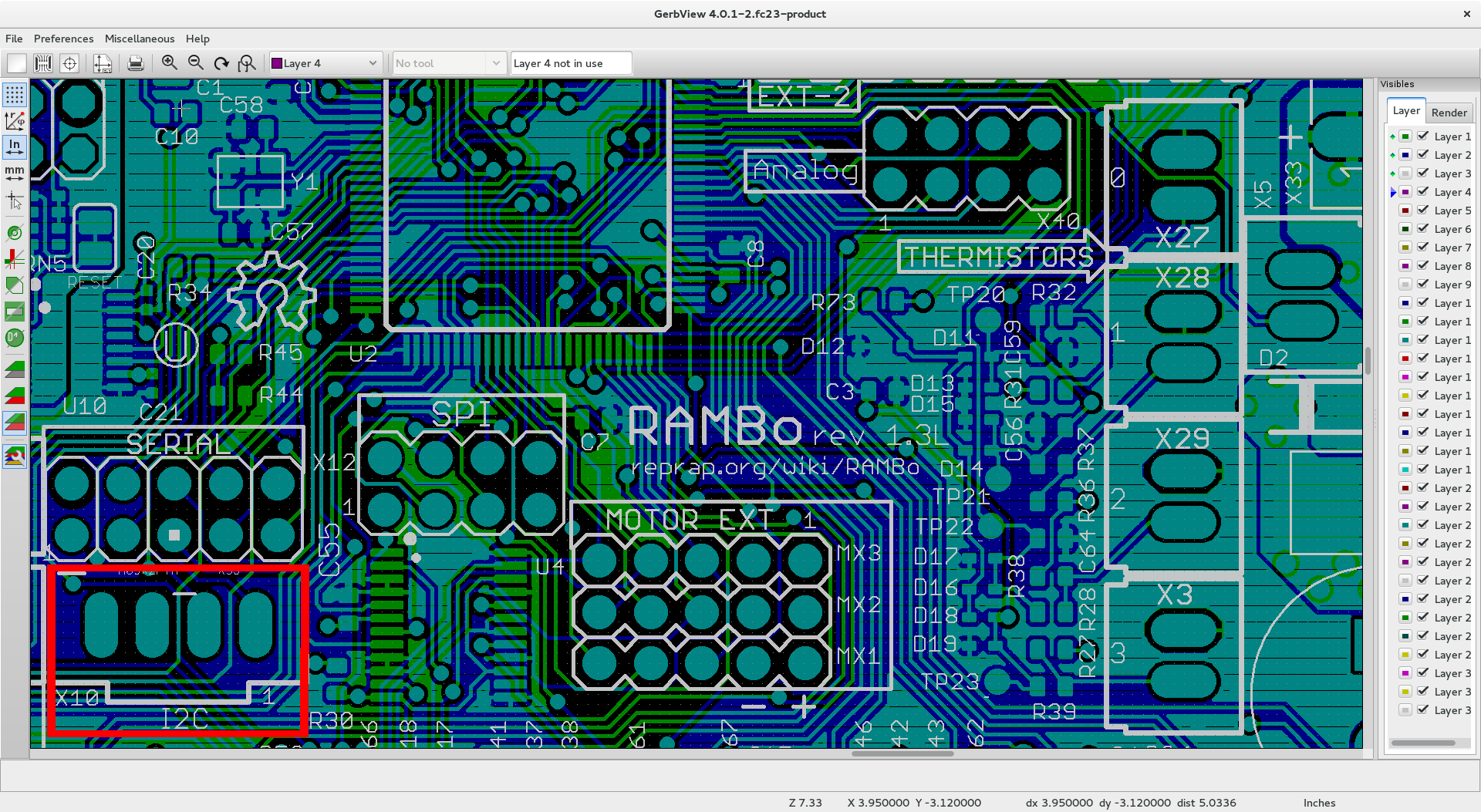
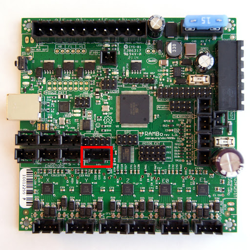
The header can be found here on the RAMBo 1.3L (“I2C” is silkscreened just below the header):
Make sure that’s where you’re connecting the MCP23017.
If you have any free digital pins available on your RAMBo then you can simply use those as your endstop pins rather than using the MCP23017, but it’s up to you.
The MCP23017 is connecting in the right pins. That was checked with a very simple blink sketch and with the M119 statement.
By printing a message each time when the mcp is called in stepper.cpp I saw that the function “ISR” (The Stepper Driver Interrupt) failed whith mcp directive.
It seems when or where this interrupt is called the object mcp is not known.
At this step, I gave up because with my knowledge I can’t understand how this works.
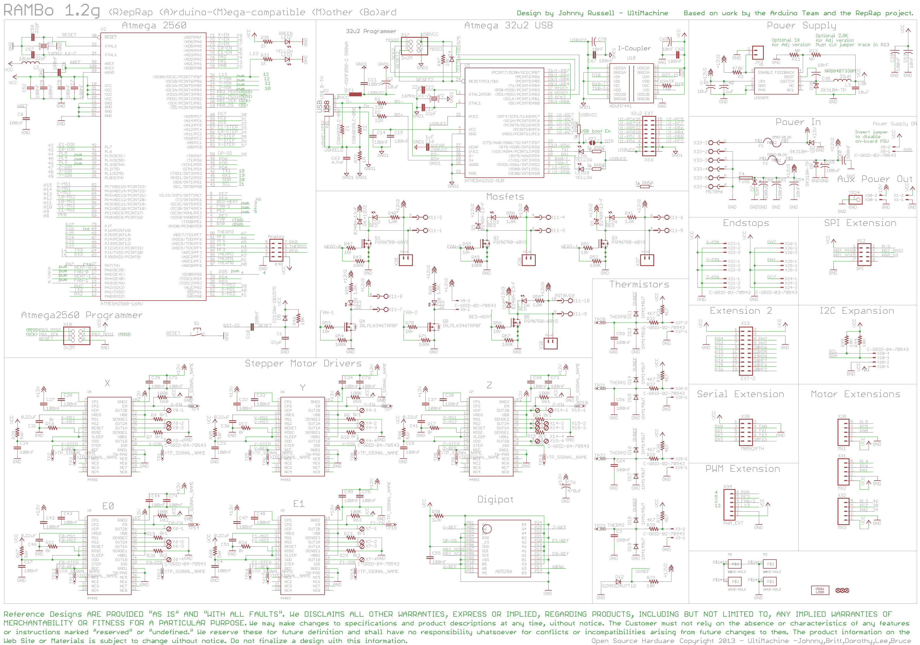
After some googling, I find this schematic and was able to identify free pins. I took A4 (58) and A5 (59). Now, I can print.
Thanks for your time and your help.
P.S: If someone I’ve any idea about why the change in the function ISR doesn’t work, I will appreciate a reply.
By printing a message each time when the mcp is called in stepper.cpp I saw that the function “ISR” (The Stepper Driver Interrupt) failed whith mcp directive.
>
> It seems when or where this interrupt is called the object > **mcp** > is not known.
> At this step, I gave up ...
> P.S: If someone I've any idea about why the change in the function ISR doesn't work, I will appreciate a reply.

What output did you see?

Did it throw a compilation error? You may need to put **_Adafruit_MCP23017 mcp;_** in Marlin.h or stepper.h so that it is in the scope of both source files its used in. The mcp object may also need to somehow be defined as volatile since it is used in an interrupt service routine.
There is no output and zero compilation error or warning. Just the Taz doesn’t work. I have to reboot it.
volatile Adafruit_MCP23017 mcp; is in stepper.h. After reading you, I thought the solution was obsviously the volatile attribut. but I got this compilation error
stepper.cpp:778: error: passing 'volatile Adafruit_MCP23017' as 'this' argument of 'void Adafruit_MCP23017::begin()' discards qualifiers [-fpermissive]
   mcp.begin();