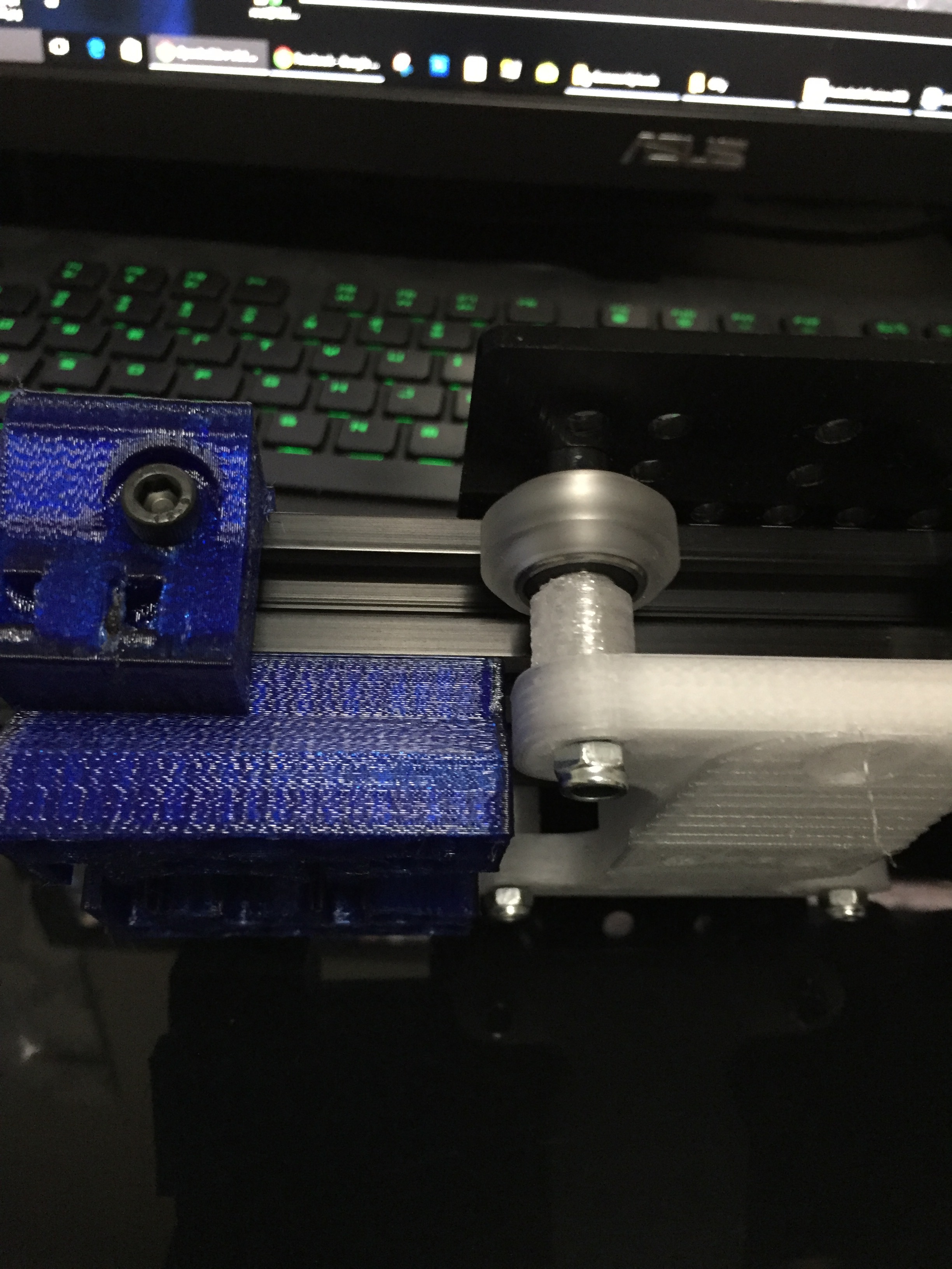
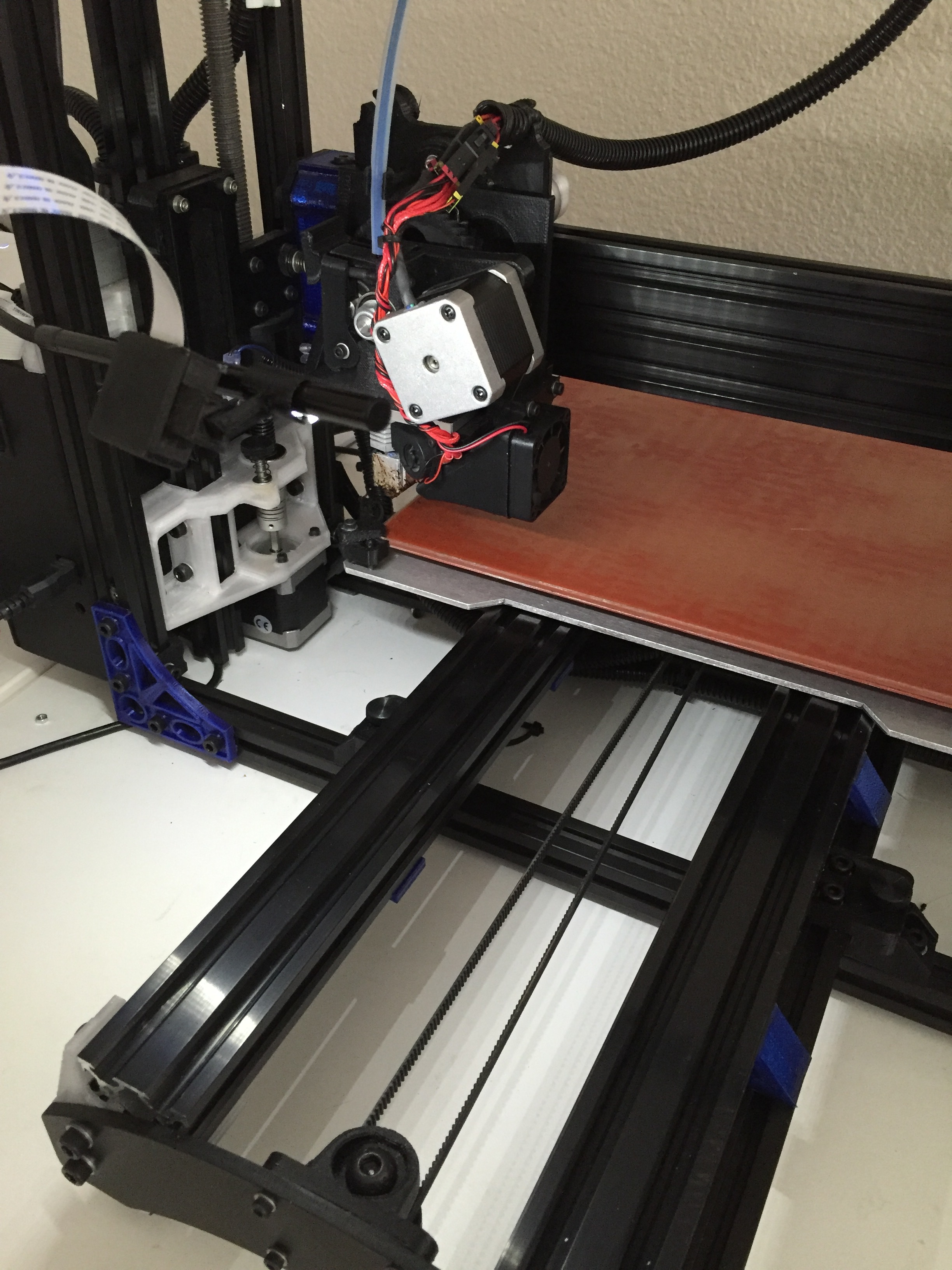
I’ve got most of the X axis built. All I need are the heat set nuts to arrive from McMaster (should be tomorrow).
@Piercet: I wanted you to take a look at what I have and see if that’s even put together correctly. My main concern is that the X endstop switch might not be able to make contact. Might be ok but just not sure.
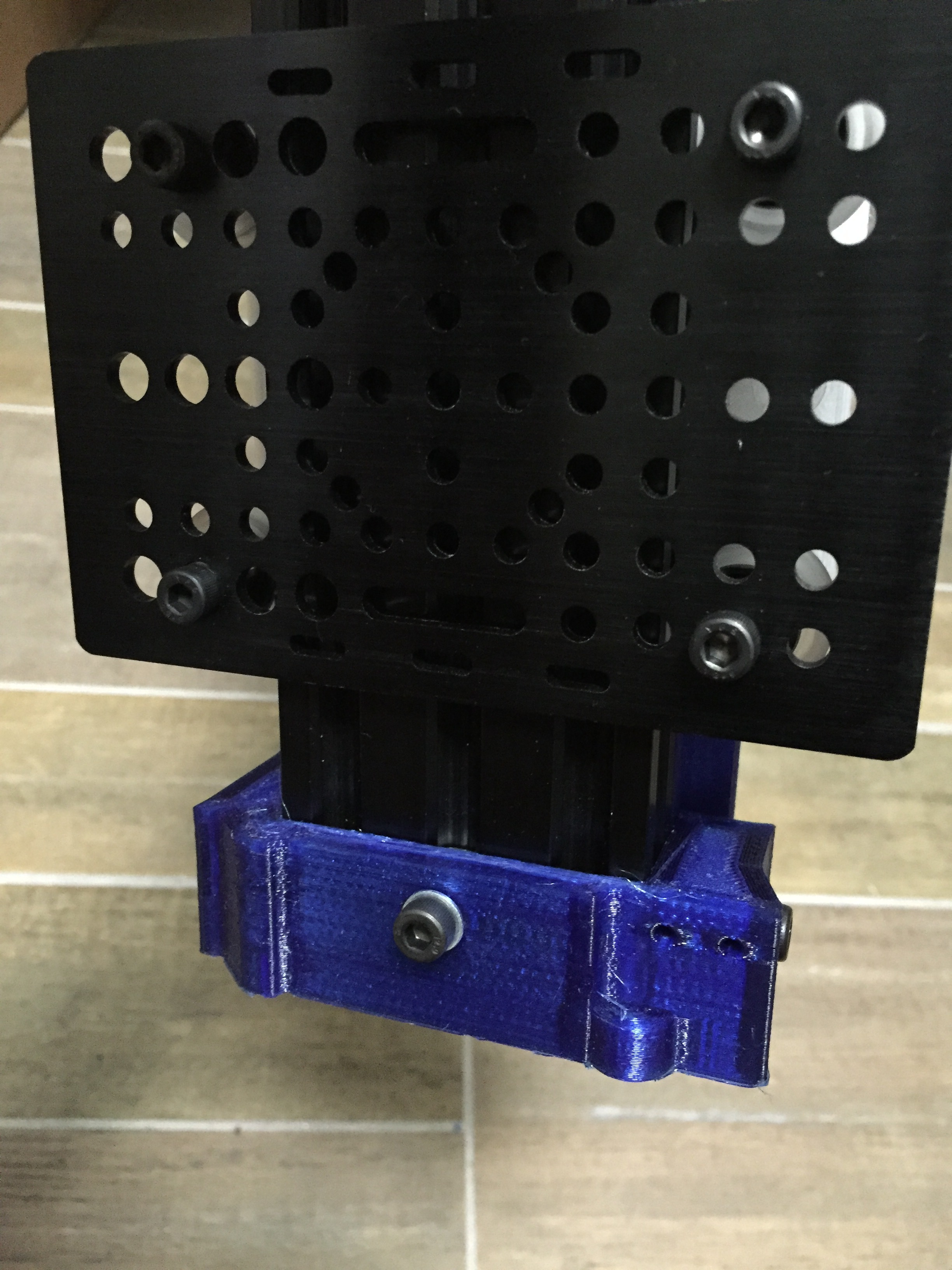
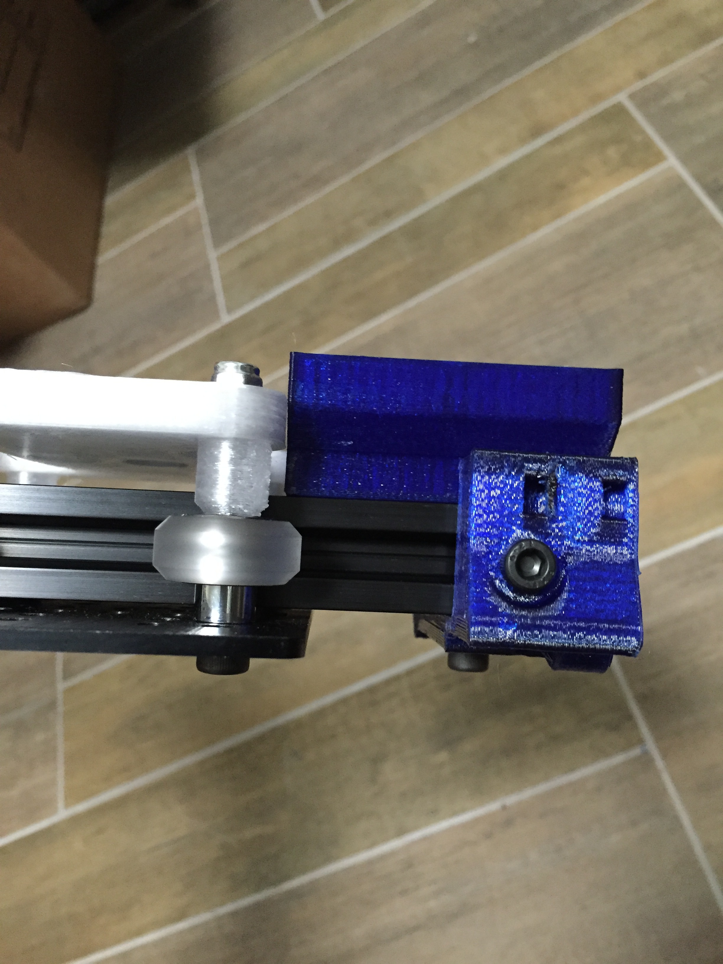
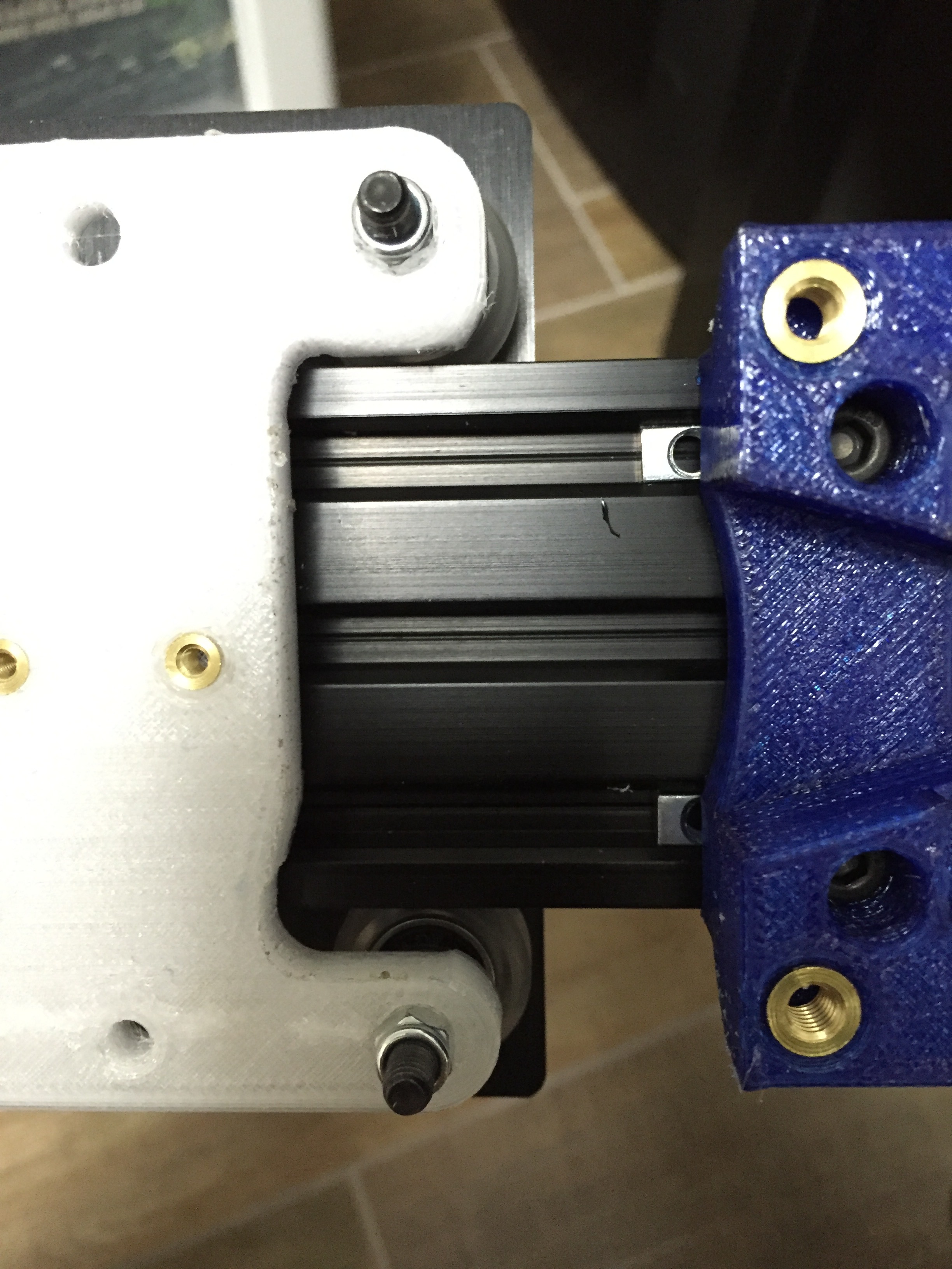
Hmmm, yeah that is a bit too far over. Looks like the upper backplate arm may be in the way. The motor mount piece should be all the way over and flush with the outer edge of the x endcap. I can’t tell if it is in that picture or not. The front mounting plate that bolts on to the front of the metal plate is a bit wider than that plate by design to contact the endstop, but I might need to make you a modified backplate. If you can, please post a picture pointing straight down to the backplate with the end cap in the frame, one from the side view of the endcap towards the backplate, and one of the endcap and the motor mount block itself and ill see if I can fit it in there. Worst case scenario you may have to use the other style.
One other thing, the front mount plate has clearance for the flat head openbuilds m5 bolts. Those standard height ones may not fit.
Here are a bunch of pictures of the back area on mine with the metal plate
Is yours hitting on the bottom and the top? How much thinner would the backplate need to be to clear on either side? I can probably drop the thickness quite a bit safely, it’s pretty overengineered.
It looks like the spacers I made spaces the piece out too far. I shrunk it from 12mm thick to 6mm and it still could use another mm or two. I’ll probably just order metal spacers from openbuilds because I need to buy some low profile 40mm’s. The 25’s that I did order were too short.
As it is, it’s able to slide all the way or almost all the way. I machined some of the plastic off on the back plate as well as lightly dremeling the motor mount
Ok, great. You are definitly close enough in that last picture with the front mount plate installed. it’s about 3mm wider on either side than the metal plate so you should get just about ideal limit switch position there.
hey im planning on doing these mods and getting ready to put in order for the parts.
2 questions
X and Y mods are complete and just needing instructions made correct?
it looks like Z axis is still a work in progress. should i go ahead and order parts for all three axes now or is the Z BOM subject to change until you get everything worked out?
X, y and z are all complete at this point. The separate z anti wobble nut is still in progress. I’m working on the instructions still. I need to take mine apart to get better pictures of assembly.
I’m concerned that when tightening the belt, it may cause the heatset inserts to rip out. What do you think about using the Lulzbot style mount? This should bolt right onto the backplate but I would really need to re-measure with everything off of the 3d printer
Adds a little weight, but i don’t see why it wouldn’t work. The Lulzbot clamp design works well on The Y axis with more mass than the X, so it shouldn’t be a problem. You could also thread the bolt from the back side of the plate and use the head and the heat set insert to keep it in place. I also considered adding a bolt cap of some sort to the end of the two bolts to hold them together, but I found with the metal backplate I didn’t need it. I like the posts on mine, but more options is always good!
That’s a good idea. I had a heat set insert in the plastic and was using a m3 screw to hold the belt. That wasn’t strong enough with just the screw alone. I dont see why it wouldnt work if I stuck the bolt in from the other way though. Thanks!
My solution for the belt and back plate is less than ideal but it’s able to let me print for now. Looks like my belt holder is not aligned correctly. I need to re-measure the distance between the two holes on the back plate.
How much further do you want the holes moved up ideally, and is the plate too thick at that point, or does it look like it will work as is with that thickness?
Oh i think your backplate is fine but when I made the Lulzbot style holder, I didnt measure correctly to line up with your backplate. Do you have any pointers for fine tuning and alignment? Or is the “squareness” of the printer not as important as long as there’s nothing binding
Ok, great. Since you are the alpha tester for that particular variant of the backplate really i want to make sure its working well for you.
For tuning and squareness, you definitely want to get everything as aligned as possible for best overall quality. I start from the base and work my way up. I use a small and a large carpenter square. Gauge blocks and a reeeeally big calipers to keep things aligned. Since I see you have my z axis mod on there too, I would start there. Make sure the carriage blocks run smoothly and can’t wiggle at all. You should be able to take one to the top and let go of it and have it drop quickly to the bottom. Then check that rail is square and parallel to the outer frame extrusions, and the back brace is allignef to hold it in place. Then make sure the x endplates are square with that center extrusion. This will prevent offset droop of the assembly. The x rail itself should be parallel to the base or top frame extrusions. It should also theoretically be parallel to the bed. The y mod is probably the trickiest part to get lined up. Start with the end pieces, make sure the extrusions are square, level and don’t have any humps from an out of dimension support pillar ( I had one of those) . for the taz style front mount plate, make sure the endstop edge is parallel with the x rail end mount. Remind me to build an alignment edge into the next version there.
Other than that, its basically smoothness of movement, and things not being able to move aside from how they are supposed to. If the carriage can move up or down on any corner, it should be tighter, etc.
One thing I noticed after completing this mod is that in a way it works too well. I don’t know if it’s just me, but when my print bed is heated there is about a .2mm valley that forms right down the middle, and I think the regular smooth rods unintentionally compensated for that by sagging in the middle under the weight of the extruder. So it looks like I need a new bed now, any suggestions for a good one?
I had some problems with the 3mm heat set nuts popping out especially a problem for the belt mount, so I just drilled them out a little and went with 5mm and it works perfect.
Other than that the only real problem I had was that I’m pretty sure I cut the rail a little to long so it was putting too mush pressure on the z axis rods causing one side not to move as fast and making it never stay level. Still a little to lazy to fix this one properly, but I should get to it soon.
Great work on the mod, I actually enjoyed doing it without a full write up. It took a little longer, but this way I was actually able to see how it worked and do a little problem solving rather than just follow instructions.
The X and Y rail mods do complement eachother. Without the Y rails, you will see an apperent dip in the middle of the bed because the stock Y rods also have the same amount of flex in the middle. On the stock Taz, both the X and the Y have about the same amount of flex, With the X mod in place only, the Y rods are still able to deflect down from the weight of the bed, leading to an apperent low spot in the middle.
I do highly reccommend replacing the stock glass bed with 12" x 12" x 3/16" Aluminum plate with PEI or Buildtak on top. It spreads the heat very evenly. The downside is you have to either transfer the heater off the glass to that plate, or buy a new one for $70.
I really do need to finish the instructions soon. The printed backplate was origionally intended to have a M5 bolt fed from the back as the belt mount post.
Post some pictures of how yours turned out if you get a chance!
I actually did the Y mod as well, so that isn’t the cause of the bed sagging. I put a straight edge over the top with the bed while it was heated and there was a small gap in the middle, and as it cooled the gap went away. The only thing I can think of is that the glass starts to sag under its own weight.
I’ll hopefully be able to post some pictures soon. Right now I’m working on replacing some of the parts that were a little warped when I originally printed them which are causing some problems, and I just ordered a bunch of new parts for the z axis mod and some other modifications, so I’ll be pretty busy the next few weeks putting that all together, but I’ll try to take some pictures of the process.
Did you transfer your heater from the glass to the aluminum or just buy a new heater? It seems like it’s on there really good, I’m not sure I could get it off without ruining it.
I bought a new heater since I want sure it was going to work. Also in not sure if you can get the old one off with it intact. Was definitely worth it though.