Adding an Openbuilds Openrail Y axis to a Taz 3/4/5

Sure, here you go! As a reminder to everyone, I’ll post any of the files for these open source modifications in whatever format you want them that I can generate. I usually just post the STL’s because very few people were asking for the step files.

Sorry to hear you had difficulty with the endplates and the drill guide. Someone else mentioned the existing drill guide holes were a little tight and did not leave much room for adjustment, so I have posted a new one with wider hole spacing. I’ll test it on my spare plate this weekend and see how it fits.

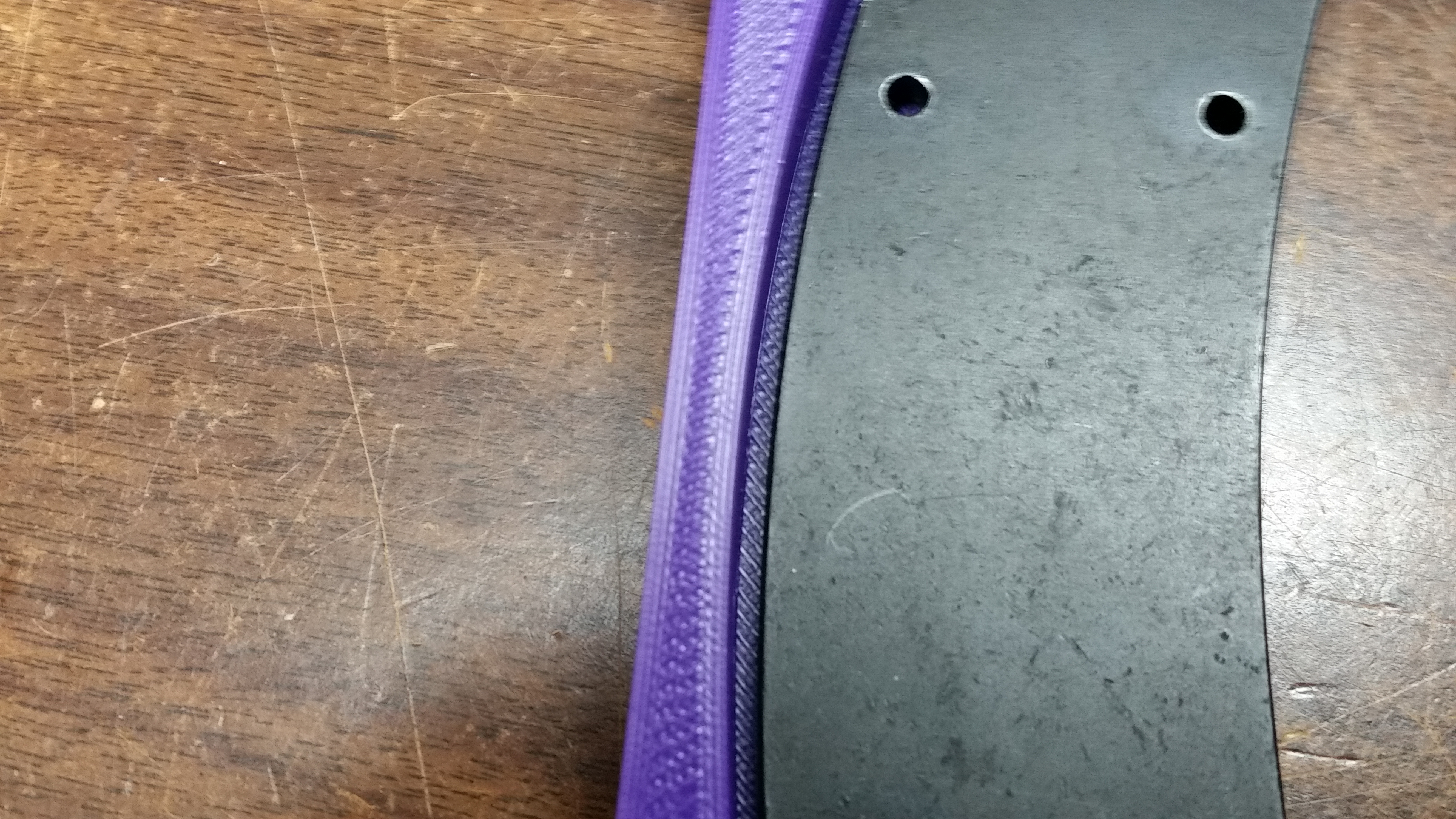
The endplate holes being off baffles me. I can’t see why they would have changed that plate. Mine started out life as a Taz 3, so its definitly feasable something changed at some point. I have a second set of plates from ITW that I am using for my mock up frame (so i can take the pictures for the long promised instructions) and it seems to be the same spaceing, no way to know what they came off of though. I’ll have to take a look at the cut files for the 5 plates and see why there is a difference. Structurally you should still be in good shape even without those center bolt. I added them in there mainky because every little bit of stability helps, but the tapped bolts on the ends of the main rails is what really locks it all in place.

Sorry about the swiss cheese bed. If it ends up affecting motion, send me a PM and we’ll figure it out. The new drill guide should help anyone else in the future.
Y Drill plate 2_0_a.stp (637 KB)
Y idler support end.stp (106 KB)
Y mod combined drill guide 2_0_a.stl (579 KB)
Y motor support bracket.stp (109 KB)

Might be due to this gap. It is hitting on both ends but the center is not. I can push the brace down to line up with the holes on the metal plate by bending the plastic brace piece down.
20160203_070029.jpg

Ok, I’ll take a look at it tonight and tweak it a bit. Thanks.

Thanks for the files! I’ve already started making some small adjustments for my version and I’ll post this weekend my experience with my version of TAZ.

Good news is that I finally managed to find the right spot for my wheels. I don’t really like the fact that I had to put them in a trapezoid form. The positions you’ve chosen are ideal from all aspects and when I had to put mine a bit closer then I knew that I was losing on stability. Especially when a print becomes tall and/or big and the resulting torque puts some extra work on the wheels and the whole bed structure. That’s why I already have a new bed coming to put the wheels where they are supposed to go.

But for now it’s working and I’m already seeing the difference.

And here is my “swiss cheese” bed plate!


Oh, and btw, the Idler Endplate doesn’t need any change. The “…2_0c.stl” file worked fine on mine. Just the Motor Endplate needs the modification.

@kmanley57: thank you for the suggestion. I checked it and it doesn’t work with me. The M5 bolts hold both Y Endplates (3D and metal) really-really tight and that kind of squeezing is not an option. I use (and love) Colorfabb Ngen. It’s ideal for dimensional accuracy, strength and stability. I would also like to use my other “love”, the Talmann Alloy 910, but the warpage for this size of a print is a nightmare.

Damnit, they are different, and off by almost 4mm. Alright, This is going to require some thought. I’ll also need to check the 4 plates. I’m thinking i am going to just have to make two endplate variants (Turns out the Taz 4 and 5 plates are Identical) for the motor side. Why the hell did they move that? Argh!

Taz 3:


Taz 4:

Taz 5:


Regarding the swiss cheese bedplate, since my holes were in the wrong spot, do you want me to cover the plate cost.

Please dude don’t even think about it!! I really hope you’re just kidding. It was my choice and my choice only to do this. And I’ll do more, trust me on this. And I’ll also “contribute” to this development because I do believe is a major upgrade and it is worth it.

Over the weekend I hope I’ll have the X axis also done and then I’ll post some more pictures and prints for comparison.

Alright, I figured I should make the offer at least heh. A new version of the 4/5 motor side endplate is in progress, should be ready in a few minutes.

Alright, here are the new machine type specific endplate reinforcements - Motor side. Also a new STEP file since apperently the one I generated earlier didn’t have the second set of upper holes.

Note: The Version 3 Taz plate is identical to the previously released 3.0c motor plate. The 4/5 variant is specific to the Taz 4 or 5. If you already printed the 3 version and you have a Taz 3, then yay! If not, here’s a nice shiny new one for you to print!

edit: Also, if any official lulzbot type people happen to ever read this post, the dimensions for the radius you show on your Taz 4/5 motor endplate PDF are a tiny bit incorrect. Since you are getting ready to use a similar part in two places on the Taz 6, you may want to check that. The drawing itself is correct, but the value isn’t.
Taz_V4_or_5_ONLY_Openbuild_Y_Endplate_Reinforcement_Motor_3_0_d.stl (119 KB)
Taz_V3_ONLY_Openbuild_Y_Endplate_Reinforcement_Motor_3_0_c.stl (119 KB)
Taz Openbuild Y.stp (861 KB)

Great! Thanks for the updated files. I also noticed that you re-oriented the offset for the upper holes on the Motor Endplate :wink: .

I’ll work on the new parts this weekend. I’ve made some thoughts but before I share I’d like to test them first.

The new ‘shiny’ new one lines up really good for me on the end plates I have. :slight_smile:

Tanks piercet!

You’re welcome!

Going to get going on this, and had a few questions.

Any idea on what length of screws are required for this build? I don’t have easy access to metric bolts, so I’ll have to order them all in.

Also, are the M5 heat set inserts just the 6.75mm length?

Looking forward to building this! That’s all for now, thanks!

Lets see, I used 30mm long Openbuilds wheel flat head bolts for the 4 wheels, Then standard M5 10mm long thread bolts for most of the other parts. The spacers (6x) each get 2 bolts and T-nuts, the rail mount ends need 2 additional bolts and T-nuts per corner (4x), then the optional front and rear plates use 4 12mm long bolts, and 2 16-20mm long threaded bolts into the tapped rail sections themselves in the front, 4 in the back. The length of the bolt there depends on how far back you tap the threads, longer is better. You may also want some short (6-8mm) thread M3 bolts if you intend to install the mini style wiper adapter at the same time.

The M5 heat set inserts for this project are the shorter ones, though there is room to use the longer ones if you like.

I would say that the use of the End Plates is critical, since they help a great deal with keeping the V-rails aligned, no matter what. The only downside on using them is that you need to tap their ends with a M5 Through-Hole Tap. Apart from the extra cost, shouldn’t you have one at hand, is the extra work. Especially if you don’t use Thread Cutting Oil.
Anyway, here is my latest list of supplies, including the End Plates:

  • M5 tap set, i.e. product# 8305A524 from McMaster-Carr, or, http://openbuildspartstore.com/tap-set/ from OpenBuilds, or, a much bigger variety at http://www.fastenal.com (i.e. Fastenal Part No. (SKU): 55617, or (SKU): 7002298, or any similar)
  • Thread Cutting Oil. If you can’t find any, then any oil is better than nothing.

Spacers (each):
(2) M5 x 10mm
(2) M5 washers (always nice to use)
(2) T-nuts
so if you use six spacers you’ll need (12) for each of the above

Front Rail Ends (Idler):
(6) M5 x 10mm (use on the T-nuts)
(6) M5 x 20mm (use upfront on the End Plate)
(12) M5 washers
(2) M5 heat inserts (i.e. product#94180A361 M5x6.7mm from McMaster-Carr will do just fine)
(2) M3 x 16mm (for the upper holes upfront on the End Plate and all the way back to the Idler)

Rear Rail Ends (Motor):
(6) M5 x 10mm (use on the T-nuts)
(8) M5 x 20mm (use upfront on the End Plate)
(14) M5 washers
(2) M5 heat inserts (same M5x6.7mm)
(2) M3 x 16mm (for the upper holes upfront on the End Plate and all the way back to the Motor)

Wheels:
(4) M5 x 30mm (I personally prefer the “Low Profile” from OpenBuilds because they’re the only ones that I can find with Full Threads)
(12) M5 washers

Hope that helps

This is super helpful, thank you!

Thank you for the detailed hardware breakdown, I’ll add that to the instructions as well.

No problem. However… I did manage to forget about the spacers…

So… for the Wheels I should have also included the following:

(2) offset spacers 6mm (for the two adjustable wheels)
(2) aluminum spacers 6mm (for the two fixed wheels)

Sorry about that.

No worries, still better than what I had up there heh.

I finally finished with the Y-modification and everything went great.
I made myself some modification to the endplate files and I’d appreciate your opinions.

First of all, I thought about changing the holes for the long bolts to slots. The reasoning behind it, is that the part of both endplates that goes in between the rails, is actually the one doing all the work to keep them aligned, since we don’t really have a unique solid piece of V-rail that will get all the squeezing between the wheels. Instead, we have a big gap that only those curved top sections of the endplates are filling up.

And considering the fact that everyone has a different set of nozzle (0.35, 0.4, 0.5 etc), slicing software/options and material, it only make sense that there’re going to be far to many different prints. These differences might be measured in a few hundred micrometers, enough to throw all predetermined holes for the wheels out of the window.

So, for all these reasons I changed the holes to slots. And now it will be easier to fine tune/adjust the convergence/divergence of the rails and finally align them before the bolts get tightened.

Allow me to share a series of pictures, where I also explain an easy way to calculate and find the right spots to drill the holes on the aluminum bed plate.


Even on the same printer with the same settings and material, the parts may come out different. This is where the Exacto knife steps in to make things equal!
After that, the first endplate (motor) is bolted and tightened really good.

The caliper helps to measure as best as possible.
And then it’s time for the Idler endplate. Only this time the bolts are not tightened.

The caliper helps to find as good as a match as possible.
Tighten the bolts and then measure again to make sure everything is ok.
This way, the alignment is as good as it can get.

And now it’s time for the aluminum bed plate and some basic math.
The distance between the holes of the original bushing is 25mm. We want to drill our holes in the middle. So, 12.5mm marked on one side, say for the fixed wheel.


Repeat the same measurement for the other end, the eccentric wheel, and we will have the middle axis on which we will drill our holes.

And now time for some more maths. Our bed plate, at this point has a width of 300mm. Our gap was measured with the caliper at about 92.60mm. The two rails are 40mm each. Judging from the OpenBuilds gantry plate, we need another 10mm for each wheel. So, our holes need to be drilled at a distance of 92.60+40+10+40+10=192.60mm from each other. Therefore, each hole on each side will have (300-192.60)/2=53.7mm from the edge of the plate. We measure that distance on that middle axis.

We repeat the same process for the remaining three holes, we choose on which side we want to have the eccentric wheels and, crossing our fingers and using cutting oil, we carefully drill the 7.2mm and 4.9-5.0mm holes.

Good idea about the adjustabiluty on the endplates!

I don’t know why, but the drill hole center marks you show on the plate look too far in. This picture

shows the correct hole position. Are you taking the cam offset into account?