Full parts list (Thank you mikronano for writing this up):
Spacers ( 6x - each):
(2) M5 x 10mm
(2) M5 washers
(2) T-nuts
so if you use six spacers you’ll need (12) for each of the above
Front Rail Ends (Idler):
(6) M5 x 10mm (use on the T-nuts)
(6) M5 x 20mm (use upfront on the End Plate)
(12) M5 washers
(2) M5 heat inserts (i.e. product#94180A361 M5x6.7mm from McMaster-Carr will do just fine)
(2) M3 x 16mm (for the upper holes upfront on the End Plate and all the way back to the Idler)
Rear Rail Ends (Motor):
(6) M5 x 10mm (use on the T-nuts)
(8) M5 x 20mm (use upfront on the End Plate)
(14) M5 washers
(2) M5 heat inserts (same M5x6.7mm)
(2) M3 x 16mm (for the upper holes upfront on the End Plate and all the way back to the Motor)
Wheels:
(4) M5 x 30mm (I personally prefer the “Low Profile” from OpenBuilds because they’re the only ones that I can find with Full Threads)
(12) M5 washers
This may be a dumb question but… Why do we need 12 spacers (listed at the top) and 12 washers for the wheels?
There are 6 spacer pieces under the rails, 3 per side. 12 is a typo.
The wheel assemblies consist of a wheel housing, 2 bearings, 2 washers and either a 6mm straight or cammed spacer. There are 4 wheels. There’s also a bolt and a nut. I think it should be 8 washers total unless you double the end washer.
The eccentric spacers are the pieces that let you August the wheel tension to the rail on one side. If its working without them i guess you technically don’t?
I have the eccentric spacers installed and the 6mm spacers on the opposing side but that only amounts to 2 spacers, not 6? From what I have built so far, I don’t see a place for 6 more spacers.
Ah. we’re talking about two different spacers here. In the context that they are used on the parts list first, spacer refers to the 3d printed plastic trapazoid-ish blocks that go between the upper openbuilds extrusion and the lower existing rail. I usually call them support pillars myself. I’ll probably need to edit that list a bit.
Nice! Looking forward to seeing how it turned out!
I’ve been kicking the idea of one more Y axis modification. A Y belt tensioner with a thumbscrew on the front plate for adjustment, and a Y max endstop target. I’ve been resisting implementing it because it will involve another drilling of a plate. But I really wish I had an easier to use tensioner heh.
I’m basically thinging a variant of this: MendelMax 1.5+ Y-ais Internal Idler Tensioner by MishaT - Thingiverse
The existing 4 bolts would be the anchor for the same style of base as that 2 bolt base, but reinforced and with a mount for a Y max endstop on the side. A fifth hole would be bored directly in the center of the 4 bolts for the tension adjustment. I know I can make that assembly shorter overall than that particular unit, and there is plenty of clearance. I use that style on my Ao-10x and it works really, really well. It means drilling the front plate though, and also the reinforcement plate if you have already printed those. If there is enough interest though, that may be my project for some evening this week.
I’m going to attempt to take this and draw it so I can use it. The plan is to cut the endplates out of 1/4 inch acrylic as a flat piece. The ends of the Y rails will need to be tapped M5x1.5 (is that right) I’ll post my progress later.
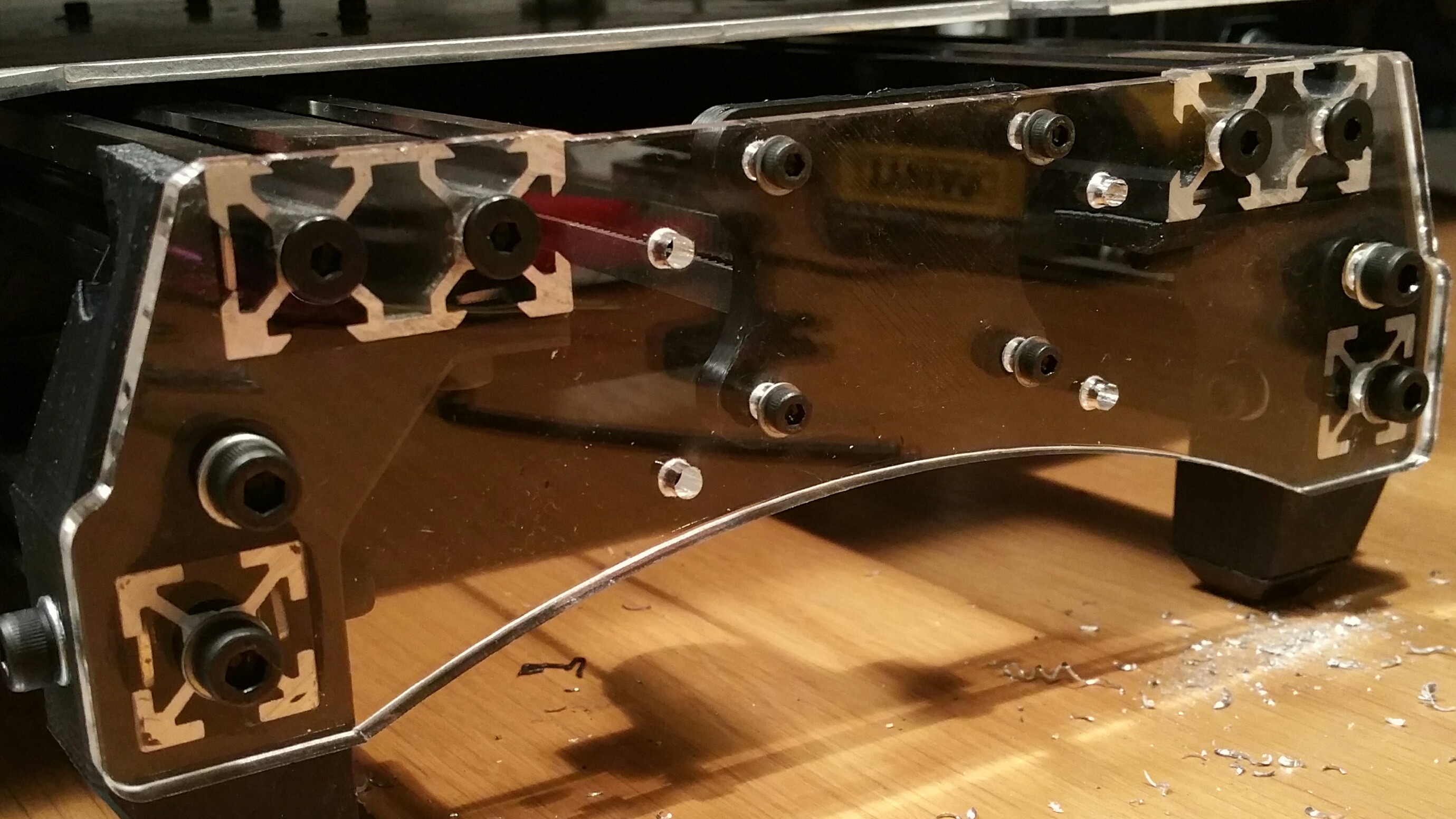
So here is the prototype acrylic y axis combined motor plate. My laser apparently has a tough time with .25" clear acrylic so the edges aren’t great. Once I get my computer back that runs the cnc router I’ll make one on it. This seems as though it will work though.
I changed some things up and it cut like butter! I need to lower the idler holes a few mm to center the belt on them it appears. I haven’t tapped the y bars yet but it is M5x0.8 thread.