You meat the X right? I think that is exactly what is happening (per other threads on this forum).
Oops, my bad. X axis is correct.
Sorry to dig an old thread up, but I modified my TAZ3 and the gcode works, except for the offset home setting. Any time I set an M206 Zx command, it still defaults to gives me “echo: M206 X0.00 Y0.00 Z0.00”. I tried setting the Z Offset via LCD screen as well, but it doesn’t have any effect. Is there a write bit I’m not enabling? #define EEPROM_SETTINGS is uncommented.
I finally got the parts printed and mounted. or the X, Y, and Z offsets I made the following aasumptions. X0, Y0 is the front left, The deployed probe is behind and to the left of the nozzle, so the X offset should be positive, Y is negative , and the probe hits before the nozzle/z minimum endstop, so Z offset is negative. My values -5, 70, -3, does that sound right? After I run the G29 script Z-offset is set 4 and the nozzle is way too high. Where did I screw up?
Ninja, you also need to enable EEPROM_CHITCHAT to write new values. If you use the LCD Z_OFFSET has a minimum value of 0.50. When making changes via CONFIGURATION after making the changes be sure to use STORE VALUES to wrtie them back to the EEPROM. I’ll take a look at the code for M206 and see what’s up.
changing #define min_software_endstops false // If true, axis won’t move to coordinates less than HOME_POS. in Configuration.h will allow negative Z values
at line 1025 in ultralcd.cpp this change lets you define a negative z-offset, down to -0.5 minimum, 50 max
MENU_ITEM_EDIT(float32, MSG_ZPROBE_ZOFFSET, &zprobe_zoffset, -0.5, 50);
M206 adds addition homeing offsets and you need to use M500 to write changes.
I still don’t have the auto leveling working right. When printing starts i get the z_probe_z_offset height, around 5mm for me. Maybe I need to define the z_offset as a negative
This is great, does anyone have a parts BOM and proven software for doing this on the TAZ 4? Will it work if I have Lulzbot’s Dual Extruder Firmware loaded?
Go to the thingiverse project in the first post , the endstop deployment one. That is all the hardware needed. I think the latest dual extruder is 2015Q1, which does have some G29 code in it. The latest stuff MESH LEVELING has not been added to the main Marlin branch yet, so it is not in TAZ firmware.
Hi,
I chose to post in here my problem, instead of creating a new post, even if it is old, because I feel somebody in here will know what am I doing wrong.
I have a TAZ5 and I have flashed the new 2015Q3 firmware with the support for the G29 and servos.
I have installed a sub miniature endstop switch on a servo, in a way to go right beneath the nozzle.


I have successfully defined the servo pins, the servo number and the angles for the servo endstops.
I have also calculated the probe x,y,z offsets from the nozzle (hotend-probe).
I have even run the M206, re-calculated the Z-offset and store it with M500.
My start gcode is:
G28 X0 Y0 ; home only X, Y
G29 ; probe 2x2 points (basically the four corners)
But, I can’t get it to work unless I select:
#define min_software_endstops false
and then on Simplify 3D set the Global G-Code Offset for the Z-axis to -10.00mm (my actual z-offset, “hotend-probe”)
I have tried to run a full G28.
I have tried to run a G1 Z-10 following the G29.
Nothing works.
Unless I do the aforementioned steps (define min_software_endstops false, z-offset in S3D), right after it completes the G29 it starts printing high up in the air, on a virtual plane 10mm above the bed plate!!
It’s like the “#define X_PROBE_OFFSET_FROM_EXTRUDER” etc, etc, in the configuration.h are just a “decoration”!
Can anybody, please, tell me what am I doing wrong? or missing to do?
Define probe as z end stop
Remove x0 y0 reference in g28 command just use “g28”
Ensure eeprom settings and chitchat are enabled
This should activate probe during g28 command
G29 command activates probe for bed leveling
Eeprom settings and chitchat enable the printer to recall the probe measurements for tram correction.
Also how I setup the “z” offset is to temporarily disable min_software_endstop for z. Then set z extruder offset to “0”. I then upload the firmware and run g28. I then manually (via the smart controller) lower the z till the nozzle is at the desired height. Then read the DRO for Z on the LCD, it should be a negative number, this will be your new “z” offset. Change it, re-upload, test. Once happy, re-enable min software endstops.
Thanks for the help ![]()
The thing is that I have already tried all these things.
I have tried all the possible combinations between G28 and G29 commands and all the axes.
I have set up the probe clearances exactly the same way you described.
I have set up the servo (motor and pins) just fine.
But, for the love of all gods and goddesses on earth, it simply doesn’t want to work with me. If not for the process I described before, the board will completely ignore the probe results (which btw are there, I can see them on the LCD, on Pronterface, everywhere!!) and starts printing up in the air, as if the probe never happened…
So, I have to admit that I’ve been beat and lately I’m trying to develop a 0.1mm touch switch in conjunction with the servo, that will allow me to probe not just the four corners but other points as well.
Sorry, your still having issues, but i think i figured it out… I just bought S3D today to use on my known working autobed leveling Taz 5 (Had been using cura). All of a sudden when using S3D it would attempt to start printing about 15mm above the build plate…
I couldnt get S3Ds autobed leveling wizard to work, it just ran a G28 command, but under process settings under the scripts tab, then starting scripts tab, I entered:
G29 ; autobed leveling
G1 Z0 ; Z goto 0
After the G28 command that was already there and updated the profile.
Bam! It ran homing of XYZ, bed leveling, then began printing in the correct place.
It seems that there may be a bug in marlin or S3D where after the G28 command the new updated Z offsets arent relayed back to S3D for some reason or arent updated, so it uses the last known position (“raise_z_after_homing” in marlin firmware) as “Z0” on the DRO within S3D. So a quick hack “LOOSELY” used, would be to tell the printer to move where S3D thinks its at, “0”. Then when the gcode is ran it starts at 0, and the printer starts a 0. Or instead of putting the “G1 Z0” in the starting scripts tab, you may be able to get by with using the “Z_PROBE_END_SCRIPT” variable in Marlin and put the “G1 Z0” there.
Confirmed: if you dont put the “G1 Z0” in the start scripts of S3D, but place it within the Z_PROBE_END_SCRIPT variable within Marlin, it starts at the correct setting. Just be sure your z offset setting within marlin are correct so you dont have a crash.
I have to admit that I haven’t thought about that! I’m a bit swamped at work these days and I didn’t have to put it to the test. But as soon as I’ll try it, I’ll let you know.
One thing only: I did try to find that variable in my Marlin (2015Q3) but I could find it anywhere. If it is something that I’m supposed to put it on, could you please tell me at which point it should go and the whole expression? ![]()
Thanks again for all the help so far!
So I’ve just ordered the BL Touch for my Taz5 and it looks like I’m going to need to delve into modifying my firmware…
Is the source currently running on my taz5 with flexystruder available somewhere to modify?
Check https://code.alephobjects.com/diffusion/MARLIN/ … looks like there is a TAZ 5 Flexystruder V2.
I have to admit, I’m not running a stock version of Lulzbot’s marlin, But rather a vanilla copy that I’ve personally adapted to my machine. This is due to the fact that I buillt my machine from scratch using the source files lulzbot supplies, and instead of using a Rumba board I went with a Ramps 1.4 due to cost and the ability to change out stepper drivers. I have had to also design my own board enclosure that mimics the original to house the ramps, heated bed bed relay and needed step down converters (12v, 5v). I also modified my ramps 1.4 board to use 24v rather than the normal 12v. They essentially run the same code, the only thing in marlin that is really different is one variable in which you define the board your using.
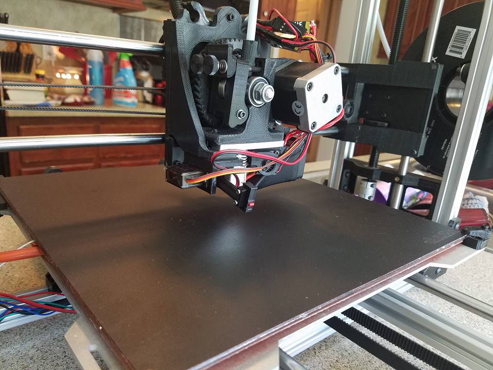
Here is my implementation of auto bed leveling. I tried to use a capacitive sensor, but couldn’t get consistant measurement readings. This has worked really well for me. And the enclosure I designed.

Can someone tell me where on the TAZ board (TAZ5), the servo pins are? I want to use one for an retractable z-probe. Thanks