Came out pretty good. Probably should have done 0.1 mm layer height for the text. But 0.2 did good.

Don’t forget to post a review of the shroud. Like, comment and subscribe! ![]()
Off topic, but we are talking about the Taz 6 so I will hijack it.
What is the point of the x max endstop on the Single Extruder? You can safely mount a normal SE toolhead on it and it works just fine without that end stop - so why does it exist on the Single Extruder?
It used to be there as a safety, but hasn’t been enabled in firmware for quite a while.
The XMAX connector is currently used as the filament runout sensor signal.
OHAI: Open Hardware Assembly Instructions (lulzbot.com)

Fun thread!
So I have everything I think I need to start the install. I suspect that BL Touch 3.1 I have is ok but I can test it via the Marlin menus on the screen.
Will your Start Gcode & firmware eliminate the spacer leveling and the nozzle wipe?
On my other machines I like a simple purge line on the left edge of the build plate and then start printing.
Actually, I suppose with these mods Cura 5.7 could be used adding a custom machine?
Yes, spacer leveling is not part of the GCODE, nor supported by the new firmware.
I have experimented with purge lines before, but I’ve come back around to full skirts.
This would work fine in Cura 5.7, but as there’s no material_probe_temperature in mainline cura, you’d want to change that to just material_print_temperature_layer_0. I think the rest of the placeholders/variables are identical. You still need to carry over the rest of the settings for speeds and quality, as well as filament profiles to 5.7. But AFAIK, the start/end GCODE will work fine.
Ok, I’ll stick to Cura LE for ease of use at the moment
It’s my Saturday afternoon project so here goes!
How do you route the BL wires on the tool head?
Also, I hate how loose the bottom is of this universal mount.
M175 Universal tool head

So the wiring of the M175 is interesting
I feel like this bundle of wires is preventing the tool head from attaching well
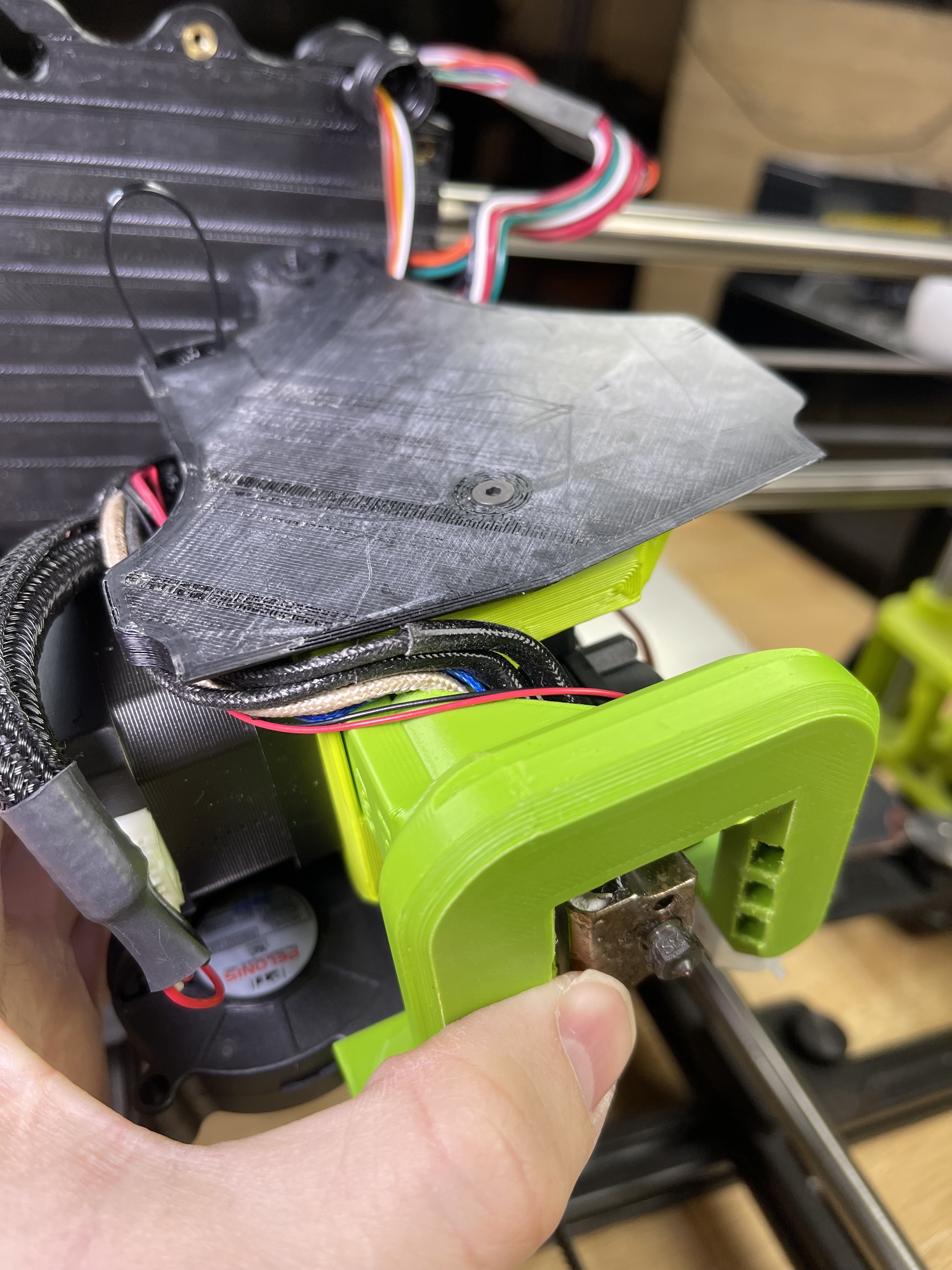
I’ve moved the wires around and when i seat the M175 into the gantry lip, I can fit in flush pretty well.
But, when I look at the top part of the Universal mount, it is off to the left of the mounting screw hole. So, if I just place it in there and tighten the screw, it is actually lifting the M175 out of the lip.

That said, that might explain my z offset being so challenging with this thing bouncing around in the mount.
New question!
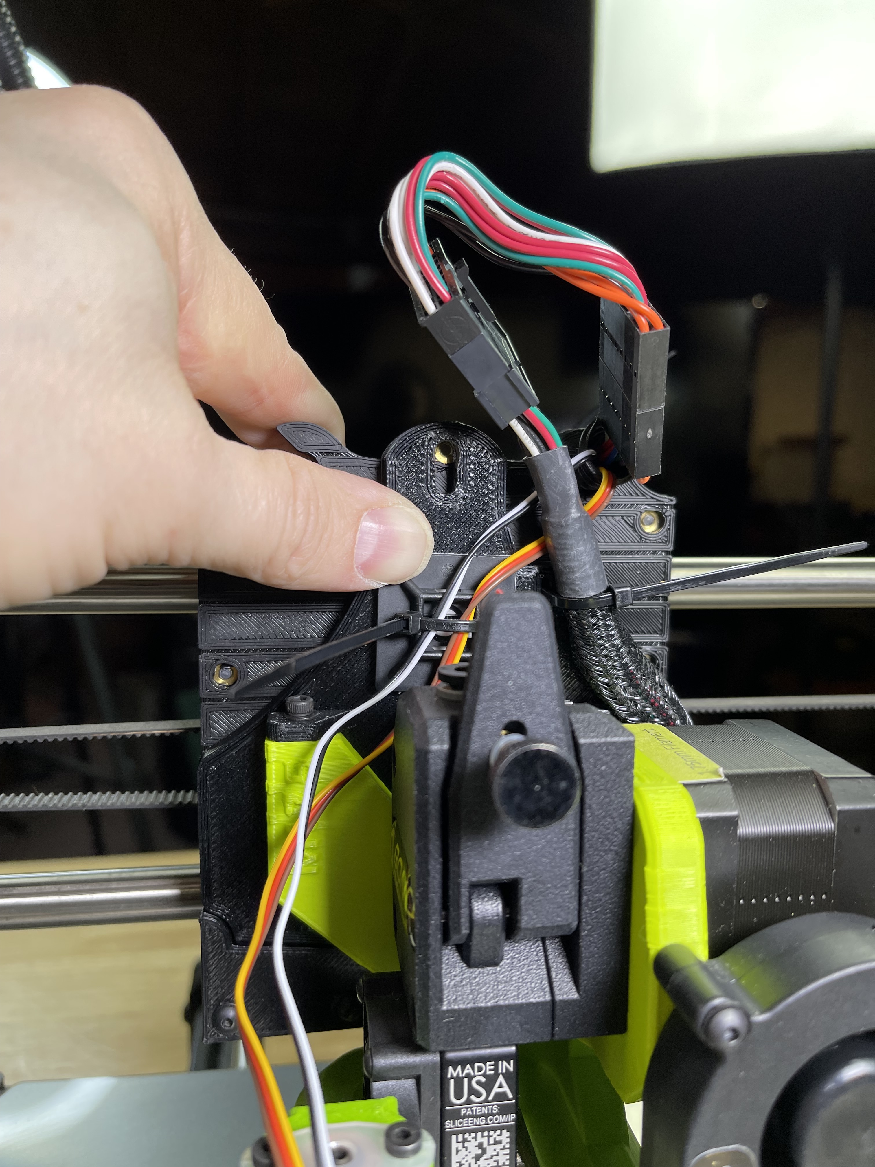
Do I unplug this connector?

I have the black / white in there. Should I use hot glue to keep it there? It seems to be staying in place.

I just ran the BLTouch wires on the side, looks about like your final picture showing them.
Yep, the old harness gets removed from the extension pins.
The black/white never had an issue coming out, but a touch of glue wouldn’t hurt.
Since it hangs out the front, you will want to do the x twist compensation wizard.
Thanks
- So that block with the red/black wire can be unplugged?
- Yes, once I get the new firmware in, I suspect that wizard is somewhere in the menus?
- Any idea why my M175 / X Gantry setup is so wonky?
- Yep. It’s removed.
- Yes, in the advanced menu for the BLTouch stuff.
- It’s fairly normal, you’ve got several layers of adapter plates, but they mostly give loose fit on the Y axis direction which the head doesn’t move in. Still, I put some double-stick tape in the little “v-slot” to make it move less before I went with linear rail.
1 Like
I’m kind of surprised they haven’t improved this method of connection over the years. When I searched about the tool head wobble, the amount of hits I got was - well - wow.
Your issues are caused by the adapter being poorly modeled by Lulzbot. You have to shim the top two mounting points with two m3 washers each for the tool head to actually sit flat on the adapter. Warning, this will be exceptionally fiddly to accomplish.
If you attach the top two bolts first and then do the bottom one, it will appear that something is preventing the last bolt from tightening all the way - like a wire or something. Tightening all three without the shims will actually buckle and bend the whole assembly.
Thinking this was an issue with the printed part being printed poorly, I reprinted it myself (in addtion to reprinting every other part). SAME ISSUE.

1 Like
Oh how absolutely frustrating that is.
On one hand, I’m glad it’s a simple fix adding two washers there.
On the other, I’m a little annoyed that issue exists. Did QC not test a Universal Mount with a M175 and see the same wobble/seating issue?
One more question - The bolt that attaches the tool head to the X gantry. Does that use a washer and what size screw should that be? I’m away from home at the moment and can’t measure what I am using but I know I am not using a washer on it (screw won’t reach the brass insert if I do)
It’s an M3, any bolt head screw will work and use yes a washer.
The plot thickens. There are two version of this adapter floating around Lulzbot’s servers. There’s the version STL linked to on the product page of the adapter:

And then there’s the one on GitLab in the tool head folder with the Aero files:

Clearly there are differences there. I am printing both to see which is correct.
EDIT: Looks like the slicer is measuring from the center of the hole (instead of the center of the surface) explaining the slight diferences.
1 Like
I’m so confused about the adapters.
I guess for now I’ll add the washers you advised and try again.
Maybe someone that works at LulzBot can chime in and set us straight
EDIT - so if you add the two washers, won’t this affect the rear screw aligning to the hole in the back of the tool head?
I added the two washers and it looks a bit more snug
However, doing so makes the rear screw unable to mate with the back threaded insert of the universal mount since it too has been lowered.
I’m curious what your test prints show.

I’m currently printing both versions of the plates and a universal “beefy” extruder mount to see what the issue is.