【MSI PRO MOD - S3】"YAZI" - Venator Class Star Destroyer

Thanks man, good intel!
So if I set the layer height to the lowest (0.14mm) and it is Z-wobble, it should be worse, getting the wobble in finer increments.
Thats an easy way of determining if it is or isnt Z-Wobble.

I will try that as soon as she gets a break from the printwork of the yazi :slight_smile:
Time flies …

An idea I have, being you are short on time. You can break your object into multiple parts. Just come up with a registration piece such as pegs or something and if you are using ABS using acetone to bond them together. Being you are cleaning them up and painting them you should be able to hide the line pretty easily. This is obviously a short term fix but the upgrades stated before are a good long term option.

Best of luck!

Yes thats a good idea for the next big build. Prevent from going to high and reassemble afterwards.
I was actually planning on doing that with the 2 reservoir holders but i found a way to do the lighting in a fully printed one.
The “head” was going to on later.
This is a good fix untill I get some cash for my planned upgrades or find a sponsor.

I am using PLA and am just doing a glue …

Great build thread so far ASPHIAX! Things are moving along quickly for you. Not much time before the 31st. Keep up the good work, I am looking forward to watching this build thread in its entirety.

Thanks man!
Yeah time flies but getting more energy out of it then I put in so its a good thing!

And to show what can go wrong if you design to fast and dont take enough time to properly analyse the part you have created in 3D.

Printing supersmooth, almost looks like a mirror with no feelable bumps or lines …

Oh shit … the 3D design is missing a single surface somewhere deep in the design …

After some fidling and testing in the printsoftware it turned out ok …

Why not use the misprint for a glue …

Laters !

**** JUST GOT REAL …

I knew those other images were fake! Ha.

Were these cut out with a cnc plasma cutter? I see almost no deflection in the smaller pieces. I am surprised

They are cut on the 6Kw laser by one of the best aluminum modders from the netherlands who happens to live 20 minutes from my house.

I totally need a 6kw laser now.

Hahaha, yeah me too, but that thing is the size of my house lol

Yeah, but you could cut out a new house with it!

Q-Switched?

Ha yes and use the laser heat as central heating :wink:

I dont know, I’ll ask tonight when we go and weld this baby up!

“YAZI” - Venator Class Star Destroyer Greebles and Lighting update

So here we are with a new update. Time flies and I knew I had to get going on these two parts very soon.
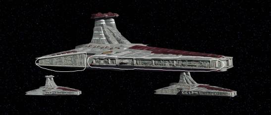
The reason why the Star Wars ships (and others) look so “real” is because of the scale and the use of Greebles.
Greebles are the little structures and depth variations and shapes you see on the outside of the models.
That gives it the sense of scale and tricks the mind into saying, hey that looks like a hangar, but wait see how small it is compared to the whole ship.
Damn that ship must be HUGE !!


So I started greebling with the help of a friend of mine Mortum. He helped create all the little single structure types that I could combine to form larger structures.
Normally you would do this with parts of styrene from scalemodels and this is called kitbashing. I did it digitally lol.

Once I had the size I wanted, I overlayed it onto the model of the YAZI

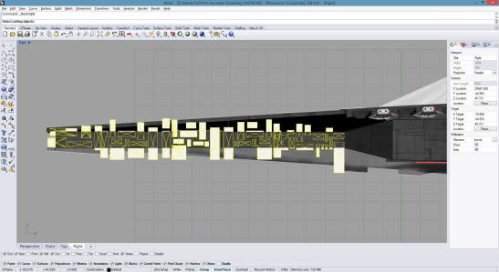
And there we have the base structure of the armour panelling.

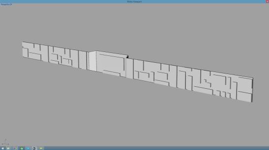
Then came the hard part. Creating shapes that resemble something that you can (probably) find on a starship.
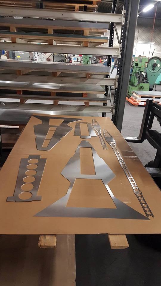
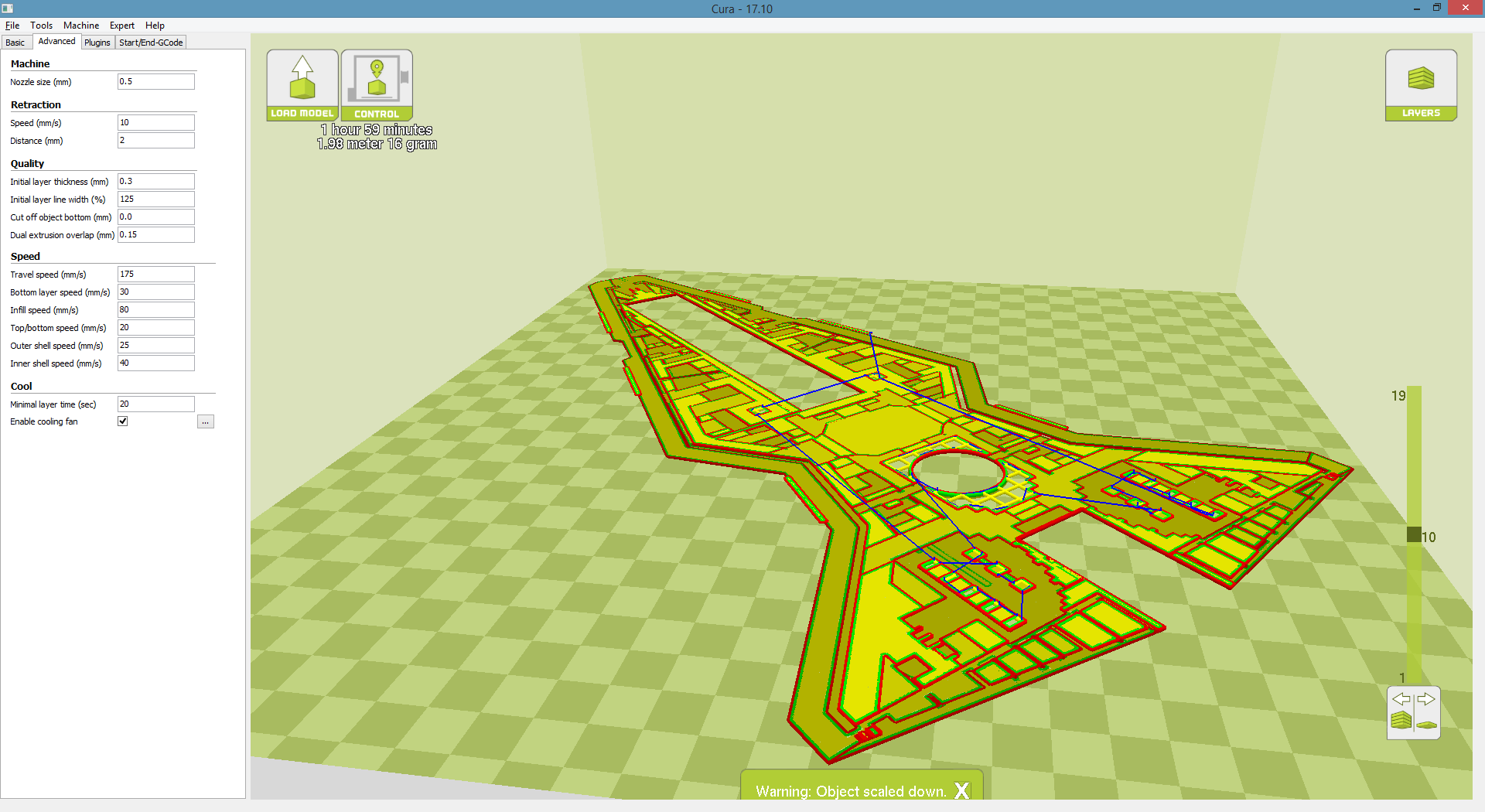
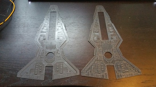
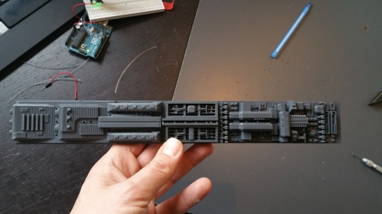
This 30 cm piece is the result of a couple of hours scaling, cutting, removing, adding, rotating parts and pieces into new shapes.

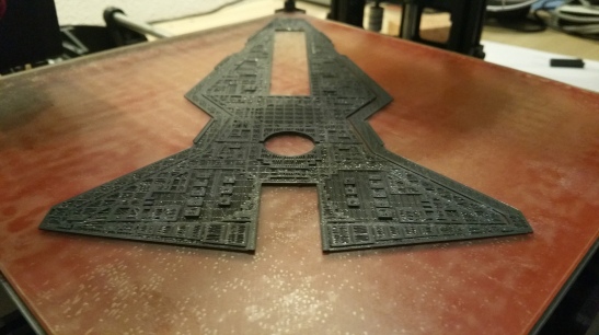
Here is the end result. I love my 3D printer. Didnt expect it to come out this crisp.
Here you can also see what I mean with “It has to mean something”

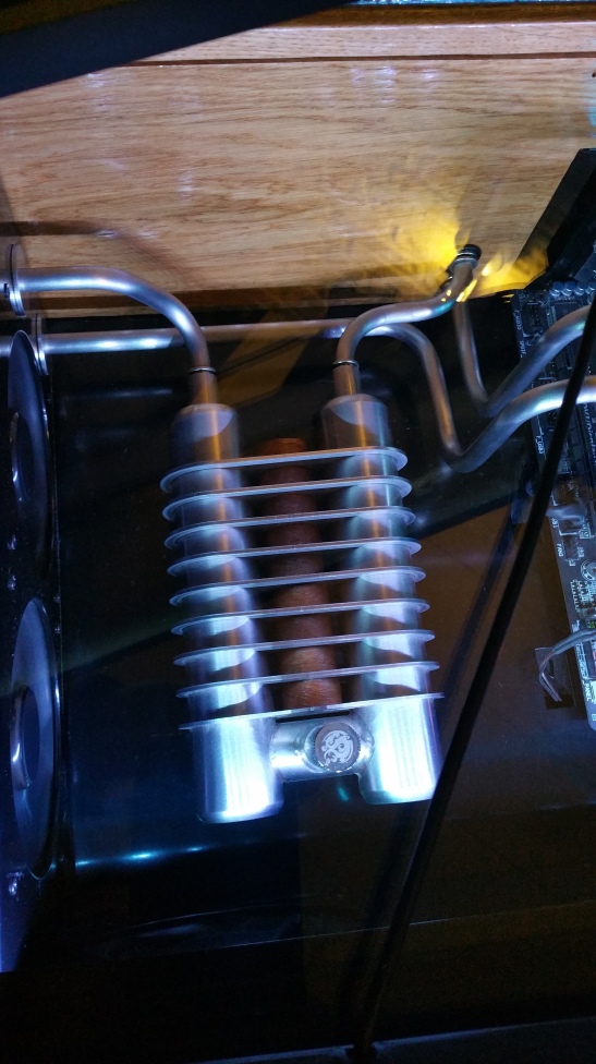
This is the mechanism for the 2 Heavy and 3 medial proton torpedo launchers.
From right to left :
You have to have some type of generation apparatus (far right) , then the protons beams have to be aligned and injected into a collection chamber (middle)
Then you need to condense and accelerate the beams into torpedo shape for firing by the launchers on the far left.

So onto the next challenge, how to light the ship properly.
First attempts obviously failed.
Tried cutting into the printed PLA with a dremel but the end result was far from what I wanted.
If only I had some channels into which I can put the fibers for the light.

Oh wait … Lets print that into the design…

In my opinion properly lighting is lighting which you can see when the light is off.
Offcourse you need some light point to accentuate certain parts but …
Getting the holes into the PLA was proving a REAL challenge …
Tried: dremel drill, Dremel with cnc mill, thin tipped solder iron, glowing wire, handdrill all didnt give the quality or speed needed to finish the project on time
PLA is different stuff compared to polystyrene thats for sure!

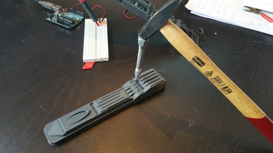
The answer : Good oldfashioned brute force. Use a very thin (just wider then your fiber) screwdriver and make sure you print the object the right way up.
You have to just break through into the cavity of the internal structure and ou on the other side!
Only took about 3 days of testing methods to figure that one out. lol
But hey, its all fun and games right …

You almost couldnt see the holes in the one of the previous pictures …

Also had to change from 0.75mm to 1.5mm fiber cable as the 0.75 was way to small for this scale.
And i didnt have a 1mm screwdriver :wink:

I love that not only you can create beautifull things with the printer, but also practical things.
Here is a fiber to led coupling. with just enough room for the led (0.2mm space left) and room for 20 fibers that will be guided by the tapered internal structure of the coupling
to the exact degrees of the led beam (60 degrees in this case) The result optimal light usage and less power needed!

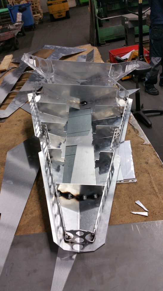
Well that was it for this one.
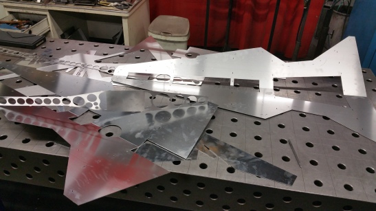
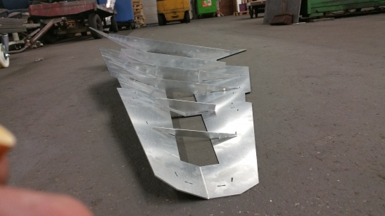
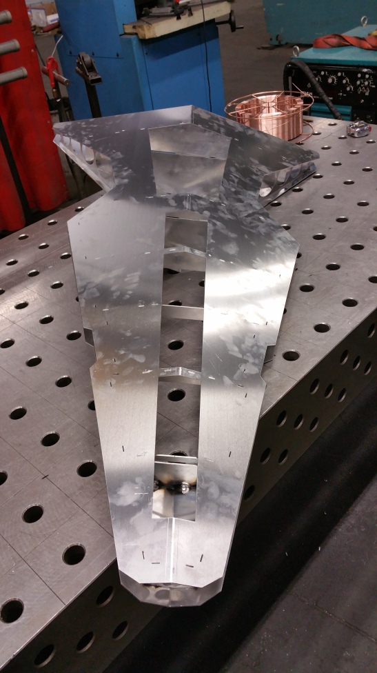
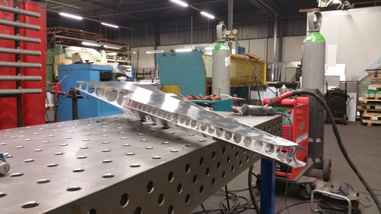
Welding the main body tonight so pretty stoked for the next update !

Let me hear your thoughts !

If you use a higher infill level, you can dremel and channel into 3d printed parts. You also may want to try raising the print temperature slightly to get better layer adhesion. At the low infill level you will use much less plastic, but you won’t be able to manupulate the part interrior as much. You can also print channels and holes into parts. Make sure the channels are fully rounded so they print without support, and if you are printing a larger hole to a smaller hole (such as for recessing a bolt hole from behind the part) make sure you include a 1mm thick solid section at the transition point, that you will later drill out. That allows the smaller hole section to fully form without drooping.

Looking really nice!

Thanks man. Thats good advice! I am using a standard 20% infill. I use rhino to design my parts and just cut a solid into the part.

Finally it was time to do the work for the aluminum body!
And who better to check your work then one of the best aluminum builders, Pascal de Greef.
After driving to his house (20 minutes) I had the honour to sit and play around with his Next Level desk. What a piece of engineering. The lifts in the legs raised the whole desk up to my chin and all the way down to my knees. Build quality over 9000000!!!

Almost reluctant we left his desk and house to start work on the body.
We had to cut just one last plate, the bottom hull …

This is the beast. 20mm steel is nothing for this Nitrogen 6Kw flastbedlaser

The main man himself : Pascal De Greef!

Then we had to do some bending

I designed the hull parts with a Male/Female connector method. Easy aligning of the parts and you also have a got place to put the welds.

Folding the sides with the large amount of holes cut out proved to be a challenge as we had to do that by hand. Learning so much about this design. Got at least 15 points of improvements for the next one (wait whut ??? That comes later :wink: )

Finally all the correct pieces in place. And you can see we had to change welding method from MIG to TIG as it was putting to much heat into the aluminum and the test pieces deformed pretty easily.
Full 3 mm aluminum next time!

To cover up all the unattractive parts I also designed a midplate which will have a black and white vinyl decoration.

I truly felt like Anakin building his podracer in part 1.

I dropped off Pascal at 3.30 am and got home at 4 am.
Thanks Pascal, your work and help really meant a lot to me. You are truly a gifted person!

The kids woke me up at 6 to find all the parts in the living room.

The fan/radiator cage I had to design to make sure there was proper airflow!

And there we have the whole YAZI built up for a test fitting.

So happy to be at this stage already but SO much more work to do in just a few weeks now.

Also all the parts of the system are starting to show up !

First the beautifull B150M Mortar by MSI and the 1200 toughpower grand by thermaltake!

Then the well designed AVEXIR 2400 Blitz DDR4 16GB RAM kit.
Cant wait to light these babies up!

Then a beautifull black and white mouse and keyboard by Ttesports.

And Finally a whole assortement of thermaltake fittings, Pacifice W1 CPU cooller, P1 Pump with silent kit, Tubler Petg tubing and whatnot…

I feel blessed to have such a group of great sponsors that believe in my ability and have enabled me to build this dream of mine! Hats off to you!

Now to start printing the Venator “Skin”

Laters!

:dremel:

Now on the printer …
A miniature (20% of original) exterior hull

Funny little print, just scaled the top layer a bit too much!

You know what the fun part about 3D printing is?
There’s always something sweet waiting for you when you wake up.

Result of the 2nd greeble sessie !