Hi - I’m going to attempt to document my adventures with a new TAZ - from first prints to prototypes for my small business.
A little background and a fairly typical story - I need to prototype, and I need things that look “production-like”. Being small, resources are pretty scarce. I needed a big capacity printer for making enclosures, brackets, antenna housings - you name it.
The TAZ fit the bill. I had one issue - I need to make parts for a demo in a month (Nov 2013) - and need a TAZ before the 2.0s could ship. LulzBot stepped up and delivered! Claudio and Rod put a refurbished TAZ 1.0 in my hands in a matter of days - while CO flood waters were still receding. My hat is off to them - thanks so much.
So here I am - I have a month to turn around some pretty nice enclosures (hence the dire need for a montage) and piece parts and I have limited experience with 3D printers. I am an engineer with over a decade of experience working for big companies that had the resources to outsource this type of fabrication. I would rate myself as above average when it comes to CAD, and an expert SW dude.
I plan to perform printer setup per the instructions, implement some of the tweaks and enhancements noted in these forums, hone my skills making spare printer parts, and then dive in to prototyping. I would love to hear any comments, tips and suggestions that you may have.
Update the settings on your connected computer so it does not sleep during a print - this became obvious pretty quickly - and it probably should have been obvious before I started.
I am going to follow the lead of some other users and upgrade the plastic bushing to bearings - I am thinking this will give me a bit more life and accuracy. Bearing noise is not really a concern for me.
I managed to make several test prints - a couple bed leveling prints and an octopus or two. Used ABS at the recommended settings. Things turned out great. It was good to do a few prints to understand the print sensitivity to home z-height.
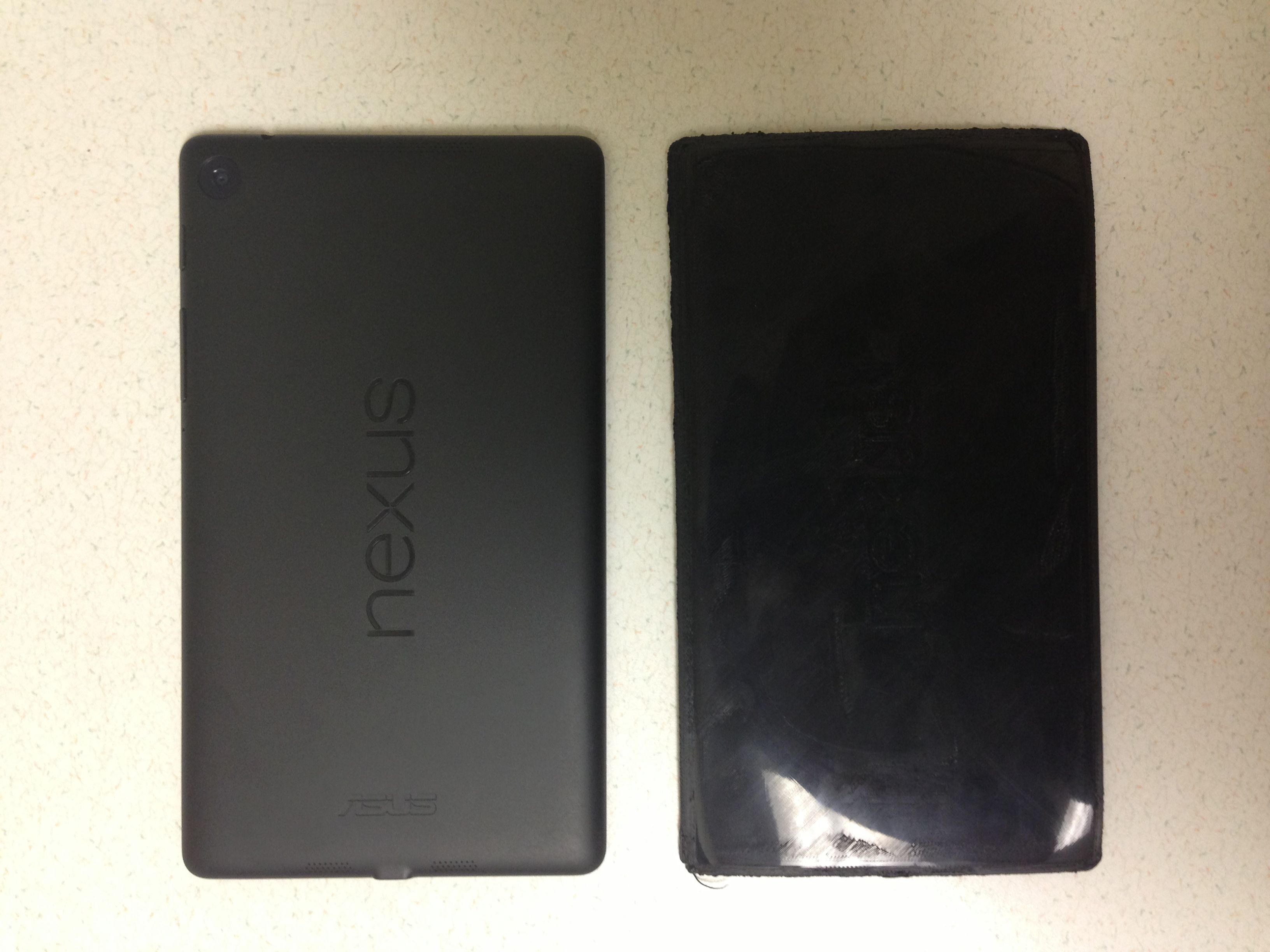
I ultimately am going to need to produce several large enclosures with a lot of flat surface area. We had a need for a mocked-up Nexus 7 - so I gave it a shot to understand what it was like to print a large flat part.
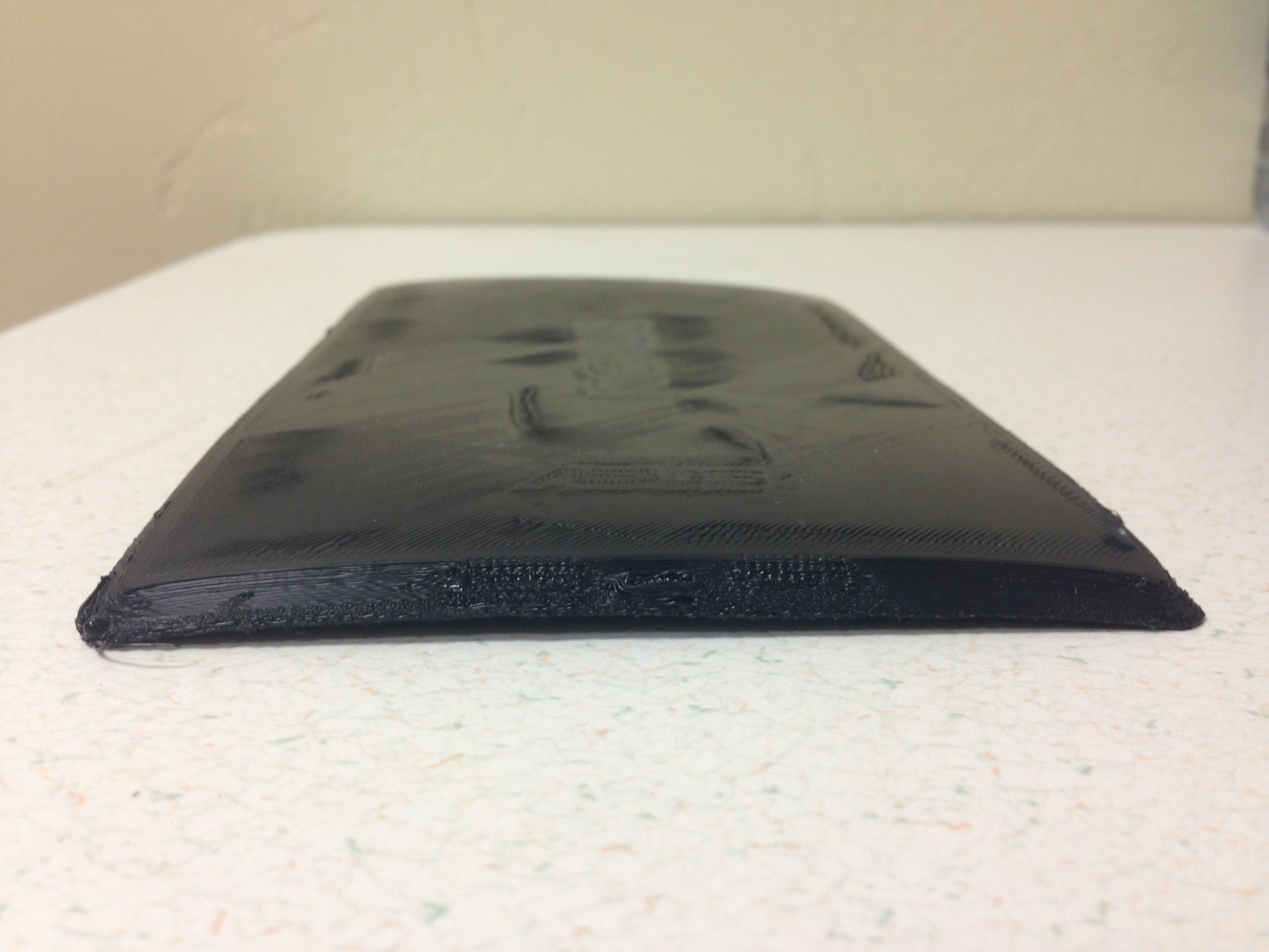
I used the .35 mm nozzle, ABS, hot end temp of 230 C and bed temp of 85 C, made the gcode and let it rip. Turns out making large flat ABS surfaces is a bit of an art. The corners of the mock up began to warp upward so I stopped the print at 92% complete.
Results are attached - Next try will be using the Acetone Glue method - the users manual outlines the steps and I found several links online. Also, my TAZ enclosure just moved up in priority.
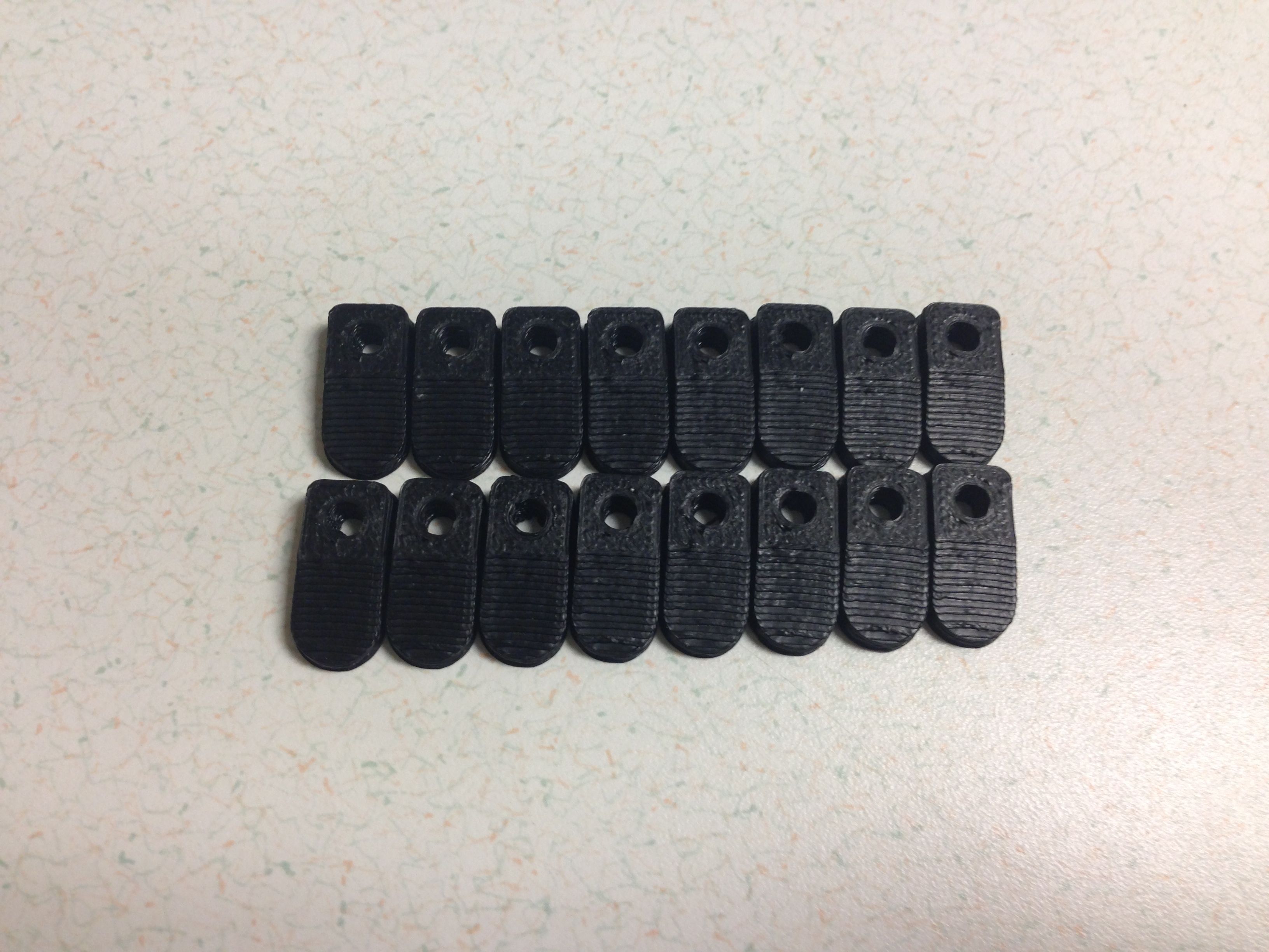
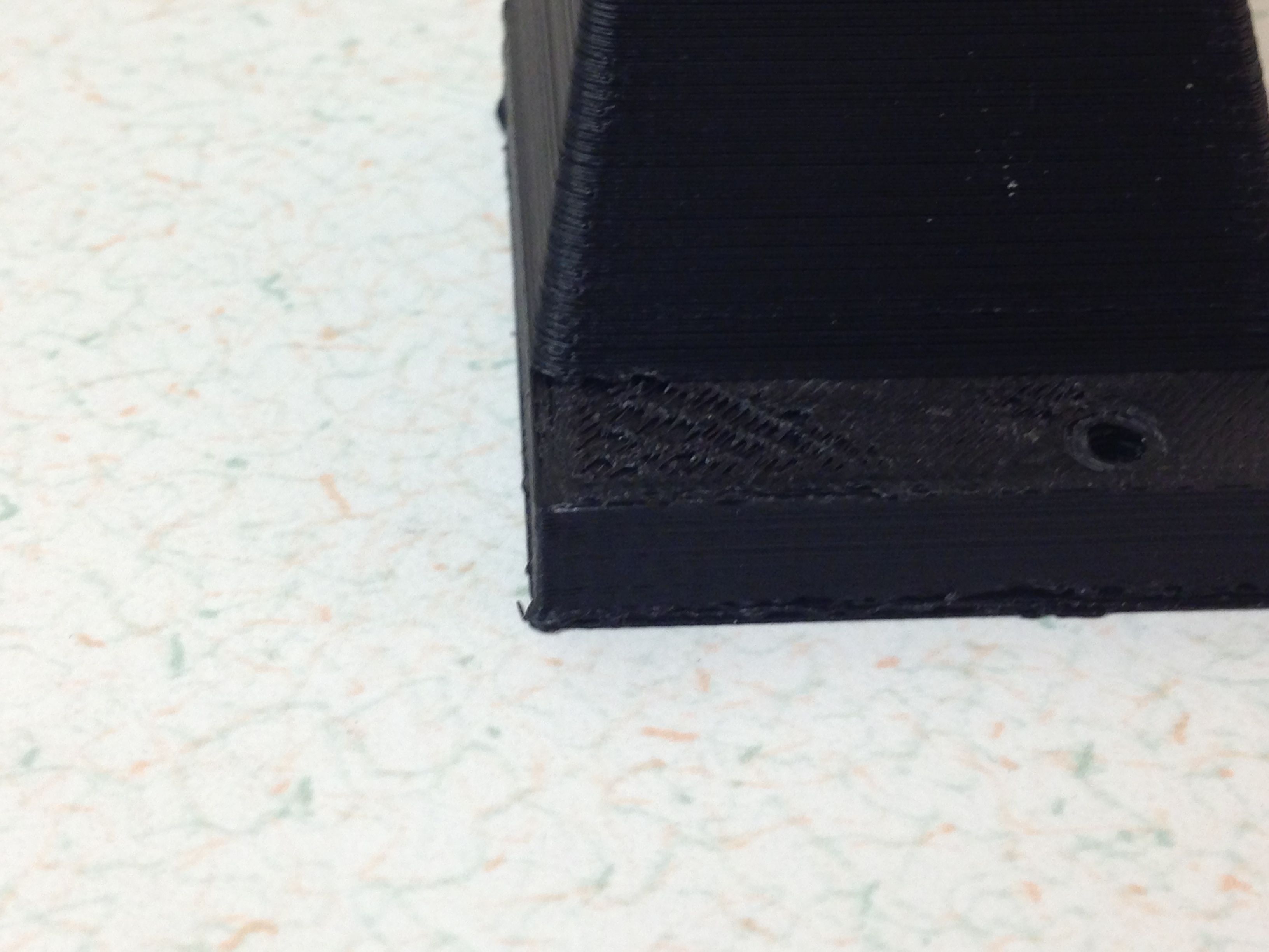
The base layer seems a little smashed - the bottom and all spares was a little wider than the rest of the part. I may try increasing the z-height when I make bed corner spares (next).
You’re probably going to want to look into some type of enclosure that can help keep drafts and maintain somewhat of a consistent heat around your TAZ one you start trying to print the larger enclosures you mention. If your experience turns out like mine, printing those types of objects in the open air may be problematic with ABS.
I get quite nice prints from my TAZ when I’m doing small parts (say 4"x4" or smaller) with minimal warping when using the ABS glue. I recently started trying to print some square enclosures that cover about 50% of the TAZ bed area. That was a bit of a disaster. The layers started cracking open as the print continued and before long, I had a giant ball of goo all over the build plate and the hotend. A friend of mine built a really nice wood enclosure enclosure and doesn’t have any of this trouble with larger prints.
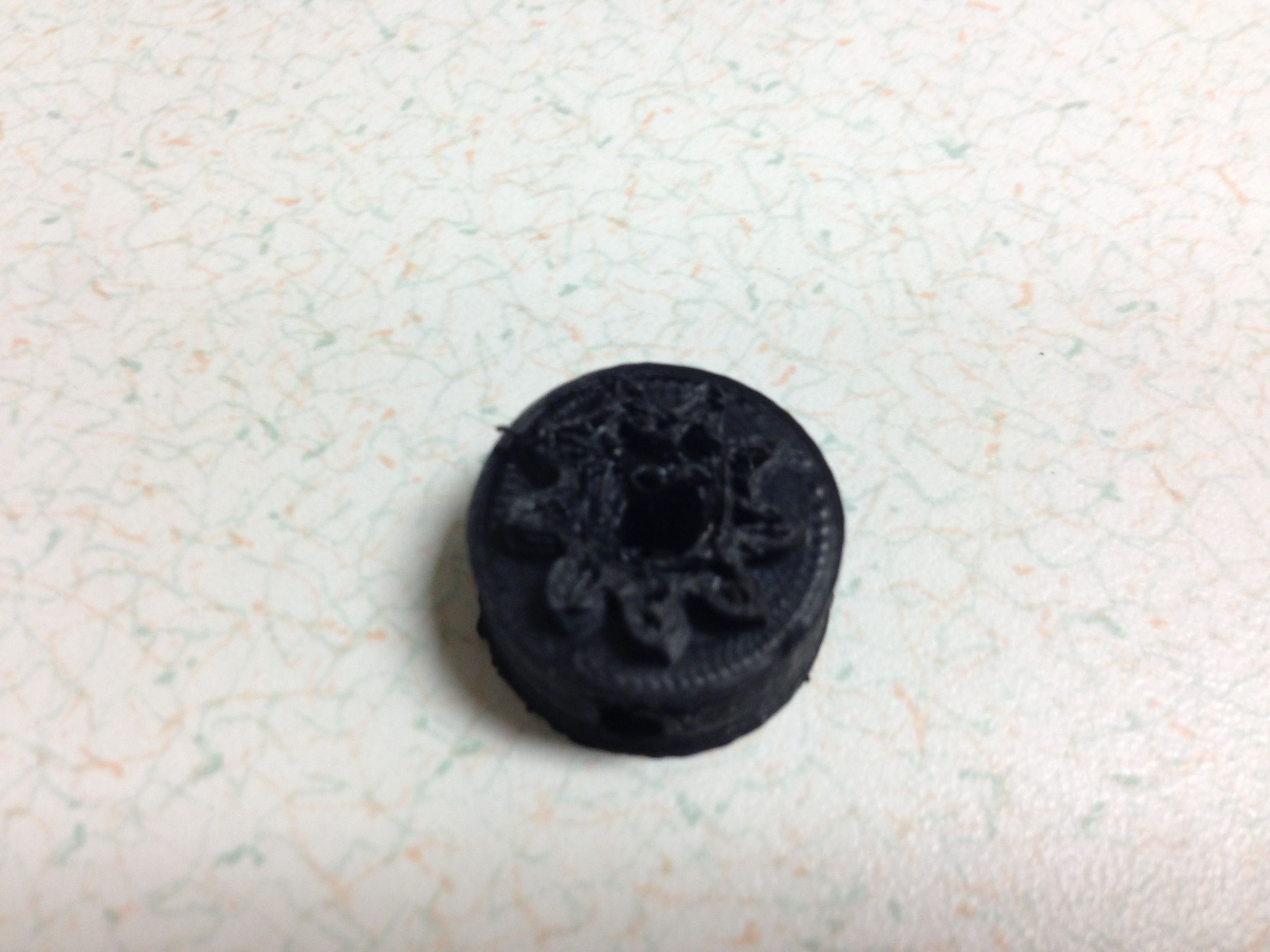
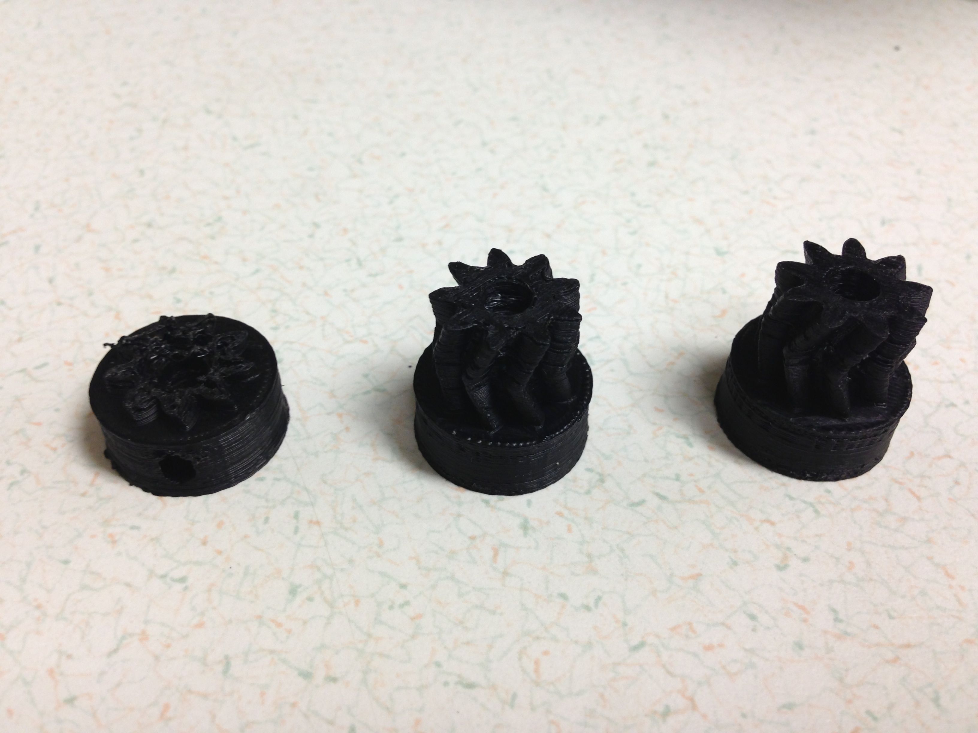
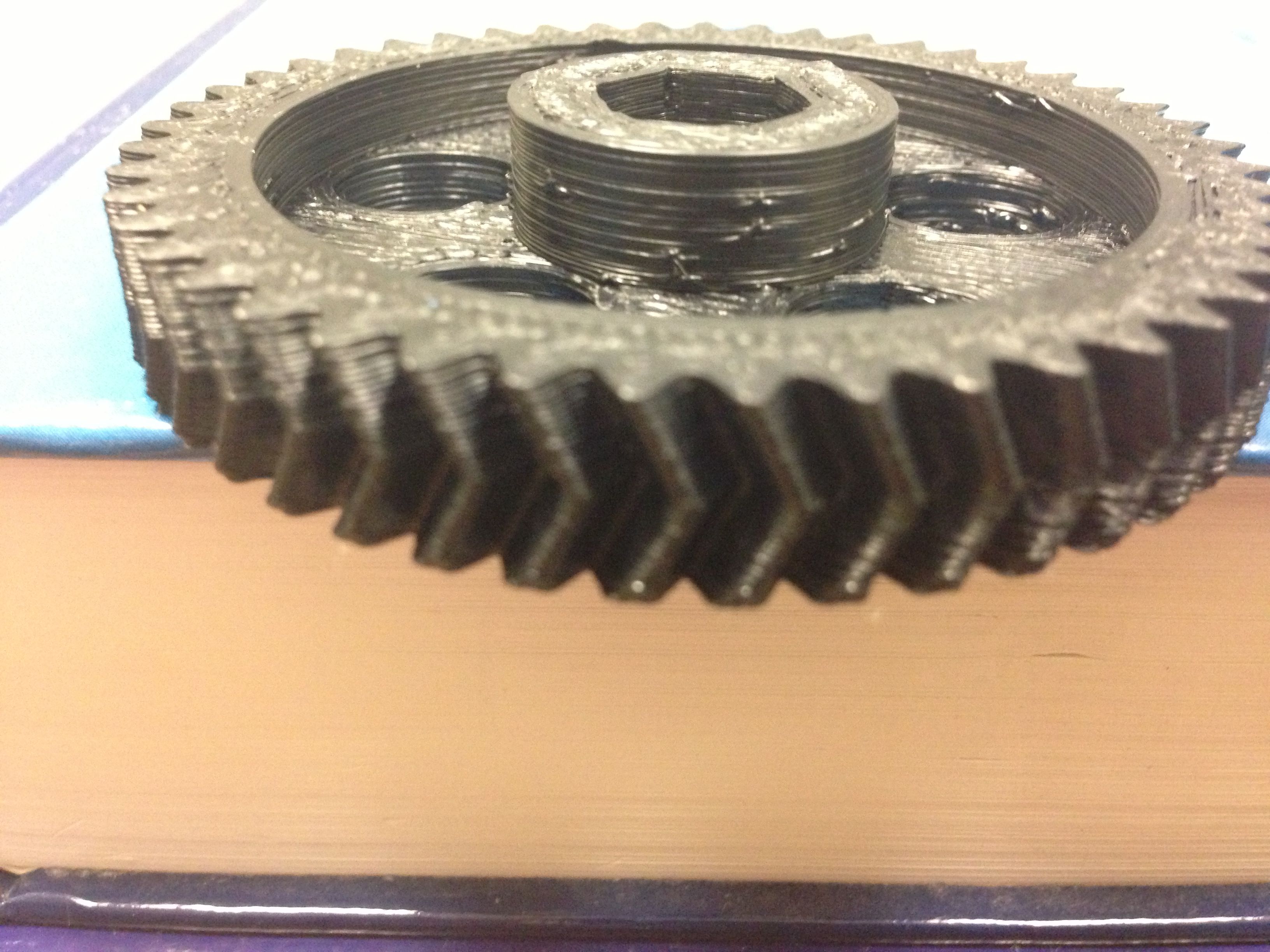
I also attempted to make a couple small herringbone gears. The first was not so good - I had the print set up with 3 perimeters - not enough room left to fill the teeth, so the part failed.
It may be hard to see - but the teeth are hollow. I updated the settings - final print configuration - 0.35 mm nozzle, 1 perimeter, .90 infill, infill every layer.
Okay - its been a couple weeks - had a trip, managed to catch a cold, and had to repair my RAMBo because I damaged it pulling fuses. But - lots of success since my last post.
Some stories and tips:
I was having some problems with fill, bridging, blobs - really just messy prints. I had performed some rough calibrations with calibration squares and thought I had things looking pretty acceptable (except for some squishing on the bottom layers). I was wrong - I tried to print the extruder idler and no dice - just messy, nothing near the quality of the idler that came with my TAZ. My slic3r config was very similar to those I found in the LulzBot download and development areas. I broke down and decided to do some serious calibration. I really liked the nickel calibration print mentioned here https://forum.lulzbot.com/t/undersized-ids/219/2 First thing I did was load new firmware with the EEPROM options enabled, which changed the behavior of the extruder. Not sure what was different (this was a refurbished machine, so maybe the firmware was old or modified in a previous life), but I think it may have been the retract acceleration. The firmware update pretty much solved all of my problems. I checked the extruder cal - factory cal was spot on - nice job LulzBot staff! The dimensions of the nickel test piece looked good.
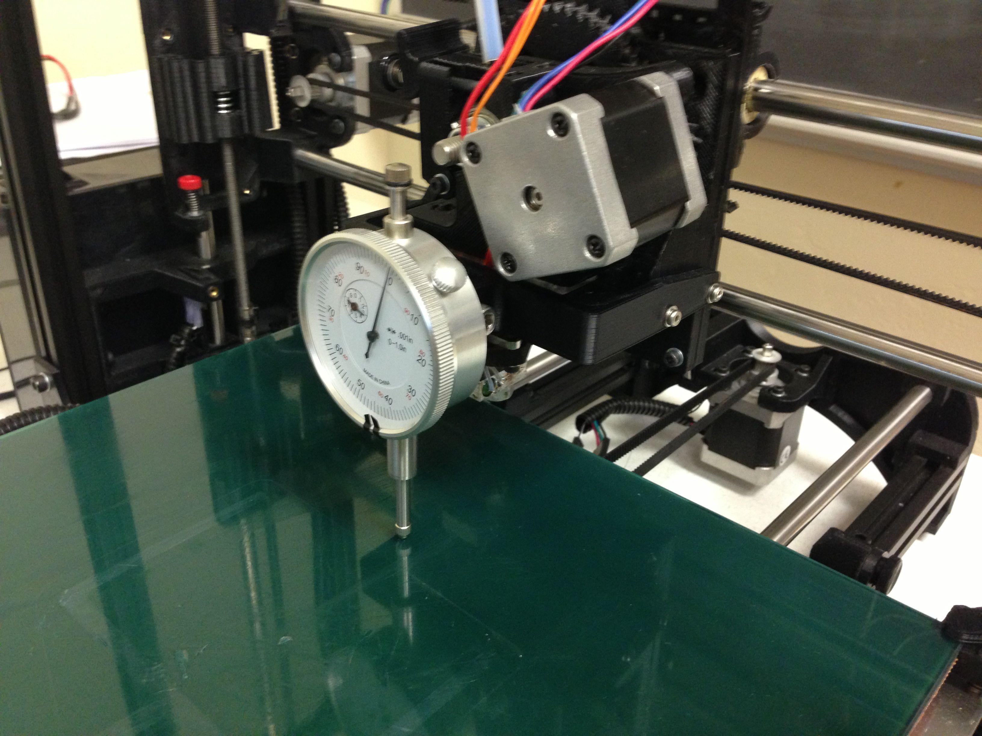
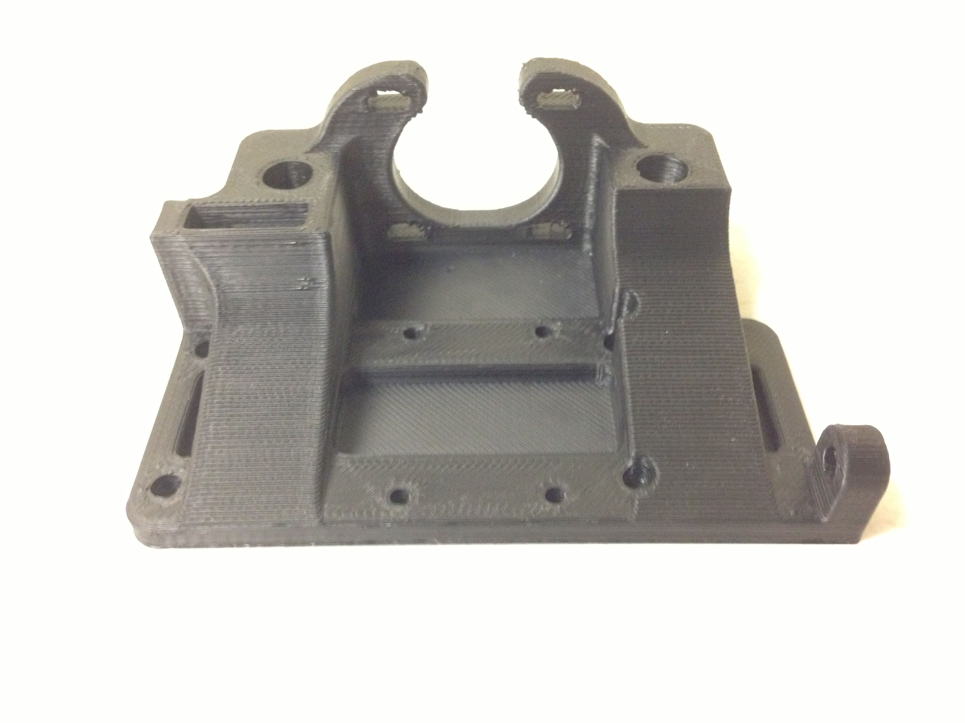
I moved on to tackling the squished bottom layers - which I suspected was due to backlash in the Z axis. 1013 has some great mods listed here: https://forum.lulzbot.com/t/taz-upgrade-list-current-and-future/204/8 The stiffened Z axis mods and the auto bed probing are things I want to tackle - I am a bit time constrained, so for now I need more simple solutions. I printed the indicator holder here https://forum.lulzbot.com/t/taz-bed-leveling/196/1 (thanks RFT!) and purchased a cheap indicator from Harbor Freight. Worked like a champ!
Manual bed leveling is a snap. I measured the backlash - 0.6 mm. After a bit of playing, I was able to get great print quality on the first several layers (no squishing) by compensating for the backlash using the z-offset in slic3r. A quick explanation of backlash - its the dead zone when changing directions of movement - so I am moving the screw down, now I want to go up - I have to turn the screw the equivalent of 0.6mm of travel for the nut to start moving in the opposite direction. Homing down means that the z-axis has to overcome the backlash to start moving up - the backlash results in no movement - hence the squished layers. Now I follow a process - first raise the z-axis at least 10 mm off the bed (overkill but good), then home, have the backlash set as a z-offset in my gcode, print. The z-offset moves the z-axis screws before printing anything. If I did things right, the z-axis is now on the right side of the backlash and moves up on the next layer. I printed several parts - including 1013’s stiffened x-axis mounts. No squishing.
I bought linear bearings, printed 1013’s stiffened x-axis motor mounts, printed the parts for a second extruder, and printed a bunch of various other spares to get more comfortable with printing.
I have some blobs - I need to play with retract settings a bit - I have the “Only retract when crossing perimeters” options set for these, which may contribute. The quality of the gear teeth is excellent - this will be suitable for a dual extruder setup.
ABS warping and print quality - I plan on building a robust TAZ enclosure in the future - For now, I have made the packing box enclosure here https://forum.lulzbot.com/t/hope-you-kept-your-taz-box-simple-heated-enclosure/170/1 I added a blanket as well - the bed heater is less active when printing and the temp under the hood is noticeably higher than room temp. I will attempt to measure temps and post results. I have had some warping - Lulz juice helped with that a bit, but I have had an issue striking a good balance between no warping and pieces adhered to the point that I need to destroy the PET tape to remove the part. I have played with skirts and brims. I made my own process - add pads to my design, heavy Lulz juice on the PET tape around the edges and in the pad areas, light coating in the middle of the part. I print the part, let the part cool (bed off), heat the bed with the part cool and remove with a putty knife. Results have been good. I still damage the PET tape from time to time, and I have gained some skills replacing nice 2" strips on the platform - found it way easier than replacing the entire PET sheet.
I think I am ready to move on to printing the enclosures I need for our November demo - more to come!
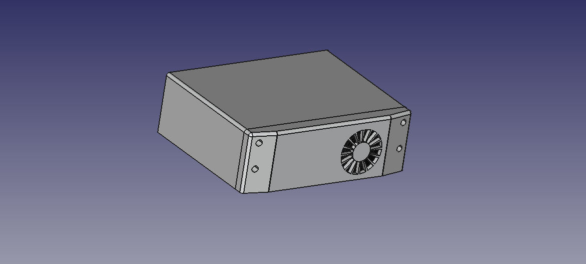
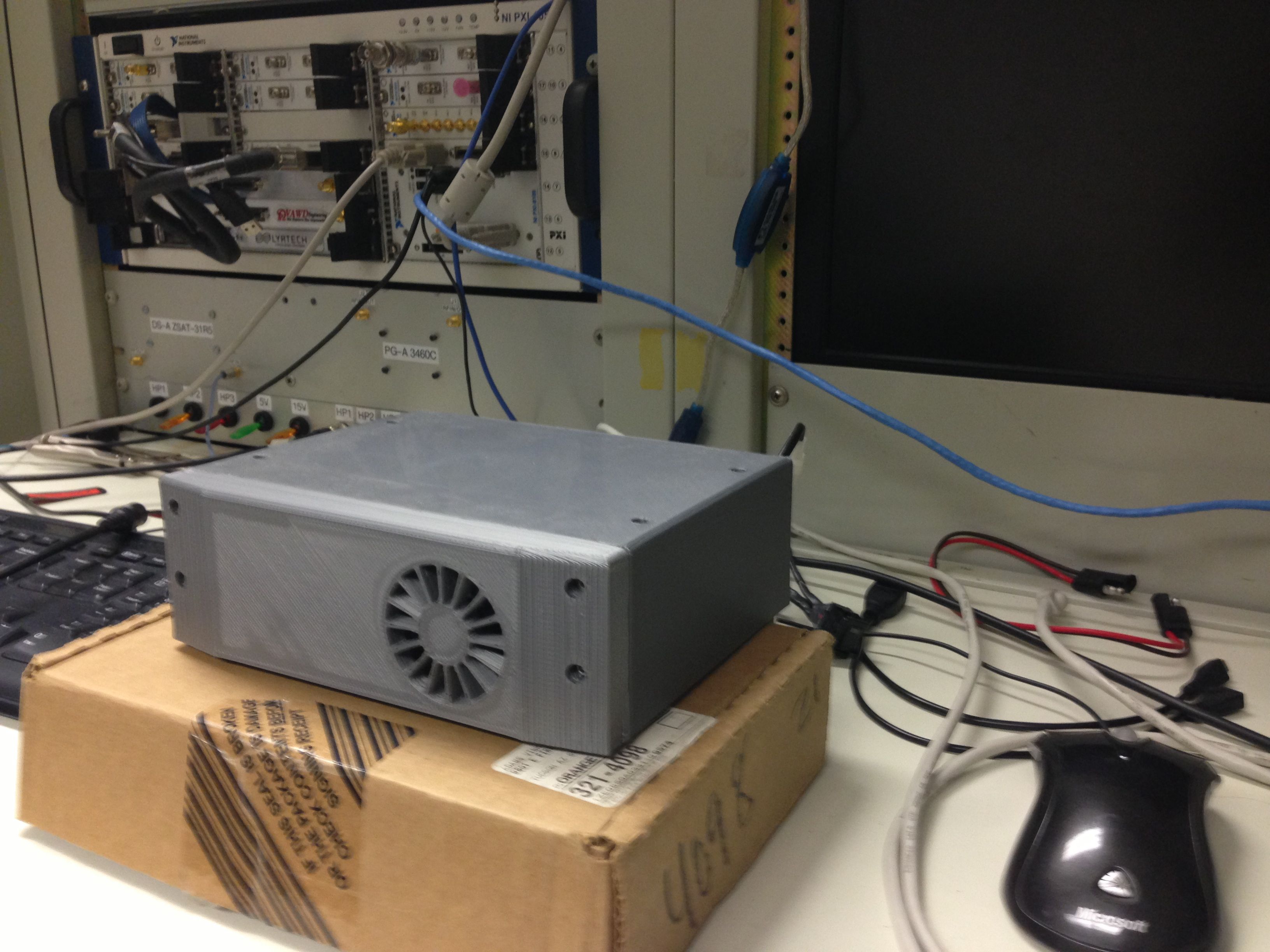
I started with our base Radar stack (we make sense-through-the-wall Radar systems!). Its a 5"x7"x2.5" stack of PCBs. It has a cooling fan and several electrical interfaces.
The enclosure is 2 pieces - a front panel and a 3-sided case (top and sides). The back and bottom of the Radar stack are sheet metal. I have plans to add our logo in a different color when I have my second extruder integrated.
I have included a tongue on the 3-sided case and a mating groove on the front panel. A couple of heat-set inserts tie things together.
The back of the front panel has a 50mm square cut-out for a small fan - heat set inserts are used to secure the fan in the front panel.
I printed this with the back down - at first I printed half of the front panel, face down as a test. The finish on the bevel was not what I wanted after support material was removed and a little acetone clean-up was performed. So, I printed with the back down and support material in the fan pocket and lightening holes. I printed the piece with a brim and a skirt. Check out the time-lapse video here http://www.youtube.com/watch?v=vcbGsMkGkR8 (sorry for the lighting - I have made some improvements to help eliminate the shadows).
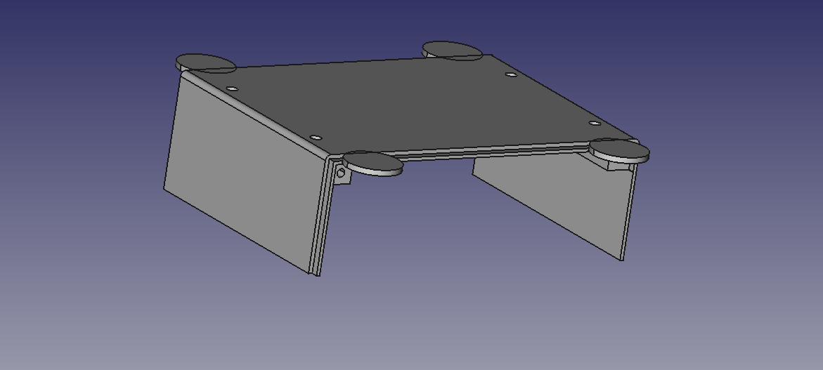
I added some pads to the 3-sided piece of the enclosure. I also added plastic in the corners of the case to replace a metal rail in the electronics stack. This gave me a nice place for some threaded inserts. The two lower holes on the front panel and the four holes on the top of the 3 sides case attach the enclosure to the stack. The top two holes on the front panel tie the panel to the 3-sided case.
Overall, I was pretty happy - the sides were straight as an arrow. No warping. No cracking. I need to improve the pad design - I think square pads would be a bit better. Some knife work and filing and I was in business for assembly.
Pretty sweet - I printed 2 front panels (first front panel was a little warped) and got it right on the first try with the 3-sided case! A couple lessons learned - 1 knock the corners of the tongue off in the design, 2 leave a little more tolerance between the tongue and the groove.
Overall - really really happy. Thanks LulzBot folks, and everyone that has provided insight for me to get this far!
I am going to start printing the hand held version of the system next week.