If you are intending on using the Anti wobble Z nut mount, here is the updated bearing carriage that you will need for successful clearance:
Openrail_Z_Backplate_2_2_c_Anti_wobble_clearance.stl (245 KB)
Piercet,
There is some stray geometry in a few of the Z-Axis files I have found. I have the files corrected and will upload them here if you want.
Please do, thanks
Working on the parts for the installation guide for this one, and making a few necessary upgrades. First up, version 2.5 of the top plates. This variant includes a cable channel and zip tie mounts for passing the overhead gantry lighting power cables and the eventual fillament monitor cable. The corner notches are to clear the Taz 5 style fillament feed tube guide. The taz 6 foldout style or older Taz 4 and earlier styles will also fit, but may need to be moved down 2-3mm.

openrail_Z_right_top_2_5_a.stl (203 KB)
openrail_Z_left_top_2_5_a.stl (203 KB)
Printable spacers for the control box Taz 3 and Taz 4/5. These move either style controll box out 5.5mm to accomodate the openbuild wheel bolt ends.
Printable_Controll_box_spacer_Taz3_1_0_a.stl (13.6 KB)
Printable_Controll_box_spacer_Taz4_5_1_0_a.stl.stl (25.4 KB)
New backplate variant, mainly adds a cable path for the Z min endstop. I haven’t figured out a good place to mount the Z max one yet.
Openrail_Z_Backplate_3_0_a_left.stl (260 KB)
Openrail_Z_Backplate_3_0_a_right.stl (219 KB)
I have seen a few mentions of the Z axis mod and the anit Z wobble mod. However I am unsure if both will work together. Or even if the anti Z wobble would help a noticeable amount to justify the install and print time.
They will work together, the Anti wobble modification is also designed to work separatly on a stock Taz configuration. If your TAZ doesn’t show any signs of wobble, you don’t need to install it. if it does show any wobble, this modification immidiatly removes all traces. The Z axis modification on its own helps a little, not as much as the X and Y modifications do, but a small amount. Whether it is worth the time and effort to install it is something you will need to decide. I can tell you that the anti-wobble modification on its own is much more popular than the full z axis Openbuilds mod.
Is there a bom and a instruction guide on this mod yet?
Not an instructions set yet. There wasn’t much interest in one. I do have a complete Bill of materials though. It’s basically 9 more T-nuts and M5 bolts, 8 mini wheels, 8 30 or 35mm long Cap head flush M5 bolts, 9 Heat set inserts (or 8 and the Micrometer barrel) and then the anti wobble parts if you end up going that route. I have most of the pictures for an assembly document, but I went off on a tangent and came up with the frame changes shown in here, so I got destracted: http://www.thingiverse.com/thing:1803781
At this point I don’t really want to take the frame back apart but if there was enough interest I could make a document. I think i want to finish the conveyor parts first though, because I got a good portion of that finished last night.
A bill of materials and some pictures is really all I need thanks piercet. If I do the anti z wobble is it worth getting new z nuts and are the 20202 x rails 500mm. I would also love to know more about this conveyor I’ve read hints here and there.
Ok, I’ll get what I have up online tonight sometime.
The Anti wobble can benefit from new Z nuts if the old ones are excessively worn, or if you want to spend the $300 and get a pair of the Anti Backlash brass ones. I don’t even have those yet.
The 20mm x 20mm extrusions are indeed 500mm long.
The bed conveyor project so far is here:
https://forum.lulzbot.com/t/a-bed-conveyor-belt-for-moving-bed-printers/3762/1
I just finished a major piece of the belt path and the Gear brake mechanism to keep the belt stationary while the bed is under motion, which were 2 of the three major hurdles to operation. I still need to finish the motor housing and the limit switch toggle points, but that’s about 90% done as well.
Basically the theory is that you would chain multiple part gcode files, separated by pause statements. When part #1 finishes, the conveyor would move to maximum Y axis, hit a switch that turns a motor that then engages a conveyor belt on the moving bed, causing the part to slowly move off the bed and onto the chute below. The bed then moves back away from the switch on y, heats up to temperature, and then resumes printing part 2, rinse repeat. The only limit at that point being available filament.
Thank You so much! that conveyor system is on the list of things to do now, after the z and the y of course.
Here’s the updated Bill of Materials
Z axis Bill of Materials
6 M5 heat set inserts http://www.mcmaster.com/#94180a361/=zhts4o
4 3/16" 1 and 3/4" long steel shafts (locally sourced from Ace Hardware)
8 Igus 2MTRI MYI-03-03 Flanged Bearing, 3/16" IDx 3/16" L (ebay)
8 1/4" threaded nylon spacers, at least 1/2" length
8 bolts that will fit the threaded nylon spacers
Openbuilds Z axis:
8 Xtreme Mini V Wheel™ Kit http://openbuildspartstore.com/xtreme-mini-v-wheel-kit/
8 30mm Low profile head M5 bolts http://openbuildspartstore.com/low-profile-screws-m5/
2 20mm x 20mm x 500mm Openbuilds V slot extrusions http://openbuildspartstore.com/v-slot-linear-rail/
4 6mm eccentric spacer http://openbuildspartstore.com/eccentric-spacer/
4 6mm solid spacer http://openbuildspartstore.com/aluminum-spacers/
8 12mm long thread m3 cap head bolts
18 M5 10mm Cap head bolts (the support braces require 3 each, for double bracing, add 6 bolts and T-nuts)
22 additional M5 T-nuts (I reccommend the drop in ones for these, they make it considerably easier
12mm long Cap low profile cap head bolts (M5) for securing control box spaced out to clear boltheads
1 M5 heat set insert if you will not be doing the micrometer upgrade
12 M5 washers
Stock parts that will be reused:
The Z height set bolt spring assembly
The existing M5 bolts, washers, and T-nuts that secure the stock Taz 5 Motor mounts, and upper leadscrew mounts to the chassis frame
The existing M3 motor mounting hardware for the Z motors
the Existing motor, leadscrew, coupler, bearing assembly
Optional:
A micrometer barrel (Mitutoyo 148-507 should fit)
and some assembly pictures from other odd angles and whatnot. These are all fairly random, and i’ve tried not to include ones that are earlier in this thread.


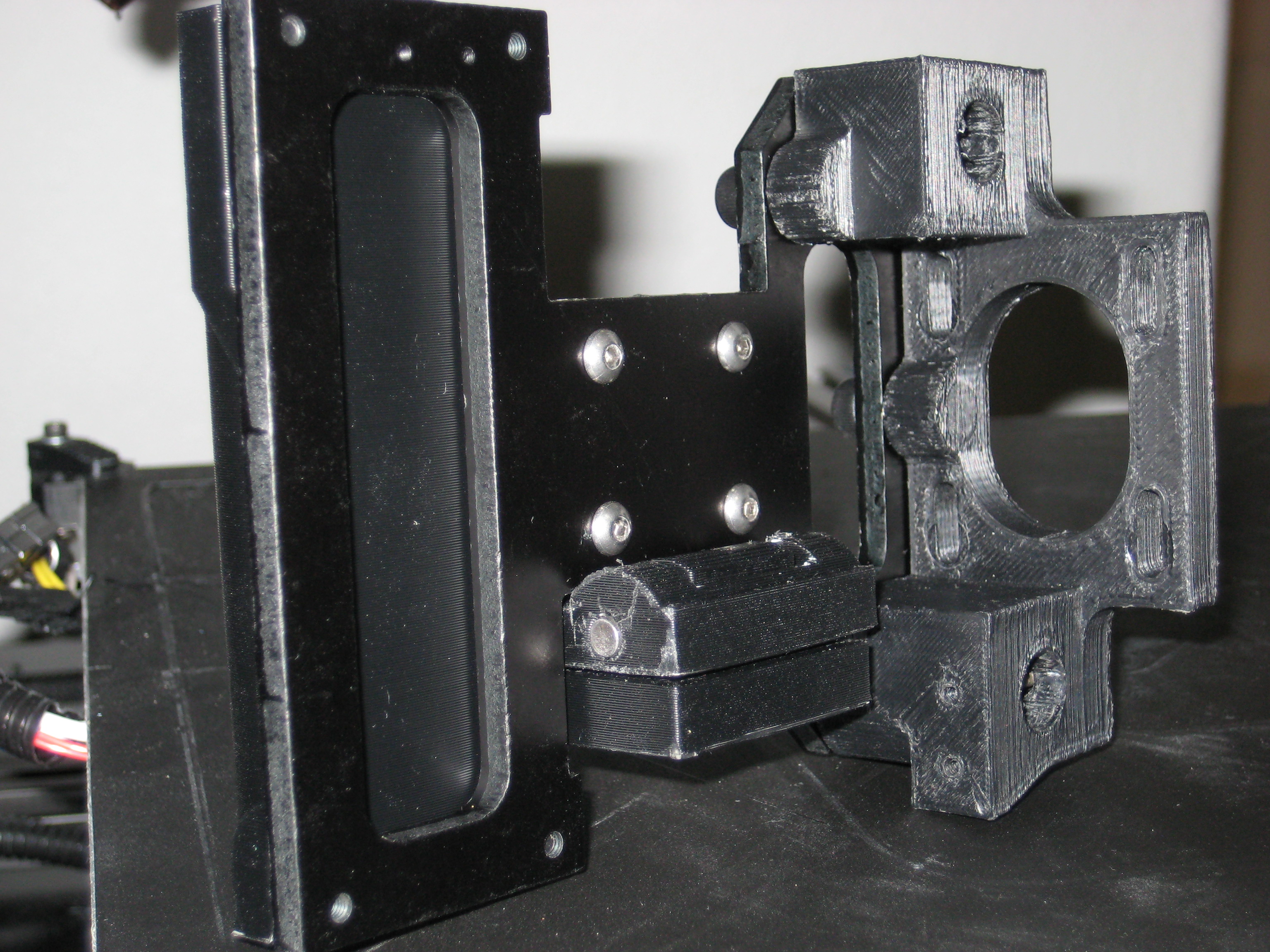


more more pictures


Those should show where everything goes. Basically the main change is you are bolting in the 20mm linear rail in place of the smooth rod, using M5 t-nuts and bolts at the top and bottm, and using 4 mini openbuilds wheels per side and a large plastic dogbone looking thing to hold the x axis to the z rail, with adjustabel cam eccentric bearings. optionally you can add the anti wobble which bolts on as an assembly where the stock Nut mounts go, and also a Micrometer barrel in place of the stock height adjuster, which i find is more accurate over time.
If you need anything else picturewise or explanations of where things go, please let me know. It is also possible that one or more of those M5 bolt lengths will need adjustment. I haven’t ran this one through my final “this is the exact length as recorded in the instructions document” process yet, so some of them are from memory.
Thanks again I will source everything I can (openbuilds was out of things) keep this tread updated with my progress.
Cool! if you get it done, you’ll be the first person other than myself to try this particular variant of it. i think it works great personally. be sure and post some pictures when you get it on the machine!
By the way did you make the aluminum z arm plates and does the aluminum extrusions from mcmaster-carr work the same as openbuilds?
The bare aluminum X end plates (Z arm plates) that you see in some of the pictures were the origional set of upgrade plates that I had fabricated by someone here in the forum who used to make them for a fee. Now you can buy them from IT works or Lulzbot Directly, but at the time no one had them for sale. My origional Taz started out life as a Taz 3. The black plates you see in other photos were sourced from lulzbot.
The Mcmaster Carr aluminum extrusions are not the same profile as the Openbuilds V slot stuff. the V slot has a V shaped slot milled into the T-Nut slot area that allow the bearing wheels to ride in it properly. It is possible to still fit a bearing wheel to a normal T slot sort of, but in this instance the geometry will not line up because the wheel would sit too far up.