I’m trying to make adjustments to the rods on our Lulzbot Taz 6.
I twist each rod manually clockwise and place the level on the printer bed but it never displays the “air bubble” in the level to be in the middle of the level’s glass display.
I have to keep twisting those rods as I keep getting that Printer Halted messages displayed on the LED screen. Eventually, after twisting those rods 1st clockwise then counter clockwise a few times that messages goes away and the PLA heats up for a print and then prints.
It’s difficult to eye-ball if the rods are even and maybe I’m placing the level at the incorrect place on the printer bed?
I’ve placed the level in what seems to be the middle of the bed but it just never displays the air bubble in the middle area of the level.
Twisting the threaded rods won’t change the print surface/table. They adjust the gantry.
Put a flat-based object, about 50mm tall on the bed on the left side. Lower the gantry so the gantry rods are near it. Turn off the motors in the motion menu on the printer, then manually turn the rods so it barely touches your object. Move it to the right side and manually turn the rods so it barely touches your object. Return it to the left side and repeat. Repeat this process until you no longer have to turn the rods and it barely touches both sides.
Your gantry and bed should be co-planar now, and auto-leveling will work as well as your nozzle is clean.
Are the gantry rods the same thing as the rods with the indentations in them on either side of the printer? If so, does one rotate them clockwise or counterclockwise to ensure the tool head doesn’t lower and press to far deeply into the silver round pad on the bed when it starts a print and before it tracks over to the wiping pad? The tool head is going too deep into that pad.
It all started with the Printer Halted message so I rotated the "turning the screw-like roads) clockwise.
The term ‘leveling’ is unfortunately misnamed, and this causes some confusion. The more technically correct term is ‘tramming’ and this term has been used in the machine tool industry to describe the head adjustment of a turret type vertical milling machine (Bridgeport style) for well over a century.
The ‘leveling’ adjustment has nothing to do with the local gravitational axis. What you are doing is making the perpendicular axis of the worktable parallel to the perpendicular axis of the plane of relative X-Y movement of the print head. It is not quite the same as old fashioned mechanical tramming, but it is close. With modern CNC control, this can be done in software instead of mechanically. The controller takes the print surface corner location measurements to determine the parallelism of the machine and stores those values to use as correction parameters to use during printing. This is more obvious if you look at a “core X-Y” type machine.
So, for example, if the gantry slopes downward from left to right relative to the print surface during ‘leveling’, the controller will compensate by moving the right end of the gantry up, thus ensuring that the plane of material deposition is parallel to the plane of the print surface.
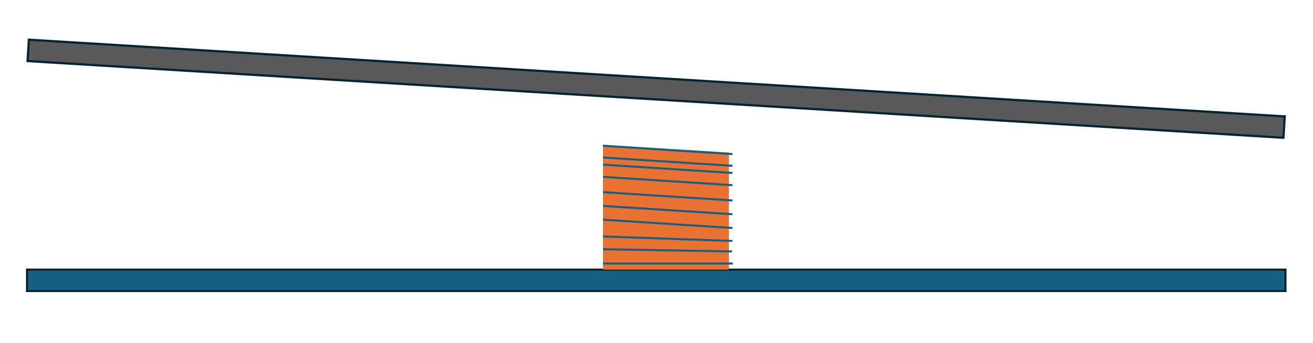
The Z motors are not driven independently on a Taz 6, so it can’t adjust the tramming automatically. Because there is a tendency for (usually) the right side of the gantry to lose steps vs the left, manual intervention is required to bring the gantry co-planar with the bed. The software has a limit on how much adjustment it will allow based on the probing measurements before throwing an error and refusing to print. Additionally, the firmware is, by default, set to fade the adjustment over 10mm, so if you’re off mechanically, a (greatly exaggerated) example of what your layers would look like is this:
Thank you for the info. I have not been inside the TAZ 6, and I really expected the Z steppers to be driven independently. It seems that I gave Lulzbot more credit than they deserved. This might be a reason to replace the controller board as an upgrade in addition to adding the microstepping capability of the newer driver hardware. I see that these newer controller boards are quite reasonably priced.
Yes, I swapped mine out for a BTT Octopus. Silent operation. I still run a single Z driver since I wanted to keep the others available for IDEX or other upgrades, but the higher quality drivers have run both motors perfectly so far.
You say silent, but those are honking steppers. My Taz Pro is supposed to be silent but it can be best described as “not as loud as a Taz 6 but certainly louder than an Ender-3 without the silent motherboard.”
The loudest part in mine is the 5015 cooling fan when it’s blowing. When it’s not, it’s the heatbreak fan. Case fan is the next loudest when it’s on, then it’s the bearings in the linear rail, followed by the steppers.
I’ve got TMC2209’s in my BTT with the stock moons motors for all kinematics.