I have been waiting to get a TAZ since version 1 came out last spring, but they always sold out, and then there was that long break over the summer until version 2 became available. It wasn’t easy sitting around waiting to join the 3D printing revolution, but it was more important to me to support Lulzbot and their commitment to libre hardware. So in the meantime I have been reading this forum learning what is involved and getting a sense that the first two things to address are making a heated enclosure and auto bed leveling. Luckily user:1013 has paved the way for the auto bed leveling, thanks 1013.
Here are some of the ideas I have been kicking around for a heated enclosure, but because I don’t have a printer, I have to speculate on some interface and usability issues.
Our bounding box for the TAZ2 is 590x508x505 (width, depth, height).
!Edit: the 508 dimension does not account for the amount the heated bed extends beyond the vertical face of the Y axis brackets! (end edit)
For the average hand to come in from the sides and grasp the frame to move it in and out of our enclosure, we should offset the bounding box by 70mm on the right side and 25mm on the electronics side. So now our width is 685mm. First assumption is that this leaves enough room to insert and remove the SD card in the LCD screen in the upper left front corner of the TAZ frame, not shown in picture. At this point you might be wondering where the filament spool is for these measurements, and I decided it is more important to reduce the printer’s footprint. Most of us have space to stack and build upward. Let’s offset the front and back by 30mm on each side, our new depth becomes 568, and even that might be too excessive.
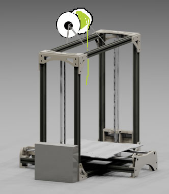
I had the same idea as user:benfarmer to have the filament spool outside and have it feed through a slot cut in the top of our enclosure. But then, to make less manufacturing processes, why cut a slot in the top for the filament to feed through? Why not have the filament sit above the TAZ completely inside the enclosure and attach to the frame of the TAZ? The frame will have no problem with the load. I just don’t know how high it needs to be for the filament to move freely when the x-axis moves side to side. You can position the spool front to back so that the filament comes off the spool tangent to where it enters the extruder. You could print the supports that hold the spool and if you double extrude, just have a longer axis for the two spools to pivot on.
I think another benefit to having the filament in the enclosure is that it will be a consistent temperature each time you use it and reduce moisture content. If you print in your garage in the winter the filament could be at a very chilly room temp or if you summer in Arizona, your garage temp could be a few degrees from already melting the filament on the spool.  Also, since heat rises, your filament sits up in the hottest part of the enclosure and your electronics sit down in the coolest part. Ideally I would like to move the electronics out of the enclosure, but for now let’s assume they will stay inside. One thing I don’t know is if it makes a lick of difference whether the filament is pre-temped or not once it hits the heating element of the extruder. Experiment needed.
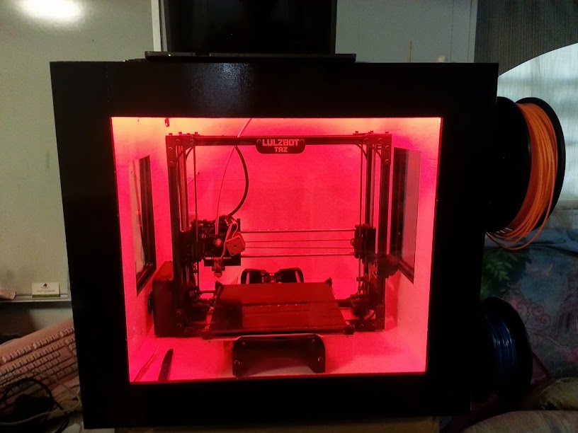
Next: moving the heat around. I don’t know how hot these enclosures will get naturally. Perhaps some of you that have one can lend some data. I also don’t know what the point is to have all your heat collect in the top of the enclosure when you really need it down around the part. Or do you want it down around your part? Will a warm draft cause parts to separate? Will a hot draft cause the same to happen? At what temp does the ambient moving air inside the enclosure need to be to provide the benefits of something like a sous-vide machine. Which gives us the most benefit: creating a draft-free oven like environment, or a drafty convection oven, or draft-free radiant heat from a few halogen bulbs pointed at the printer bed? I don’t have a printer, so I have no idea which we should shoot for. In the back of my head is the idea of having possibly two computer fans attached to the inner corners of the enclosures to circulate air, if all of this would actually create a benefit. What about too much heat? What are the operating temperatures for the stepper motors and the electronics? I don’t know, but I think it could be an easy fix because you can get a thermostat switch for $10 (ex: Circuit On At 120°F and Off At 105°F or what ever temperature range you want) for an exhaust fan to remove heat if it gets too high for the components, and why not have another to turn on the halogen lights (ex: Circuit On At 85°F and Off At 100°F). And while you are exhausting air, get a thin duct to attach to the enclosure so you can exhaust the air out your bedroom window in case you print in the house, no ABS fumes. A problem with lights turning on and off for heat is that if you have a webcam recording, this can mess up your exposure. I would probably use some 35W heating rods. Because the electronics sit low and close to the side of the enclosure, why not have a duct that directs exterior air to and from the electronics enclosure and the fan inside the electronics enclosure does the circulation. Think indoor gas fireplace, you have to bring air in from outside and vent it back outside. Plus, that is what I think I am seeing in user:benfarmer’s pictures.
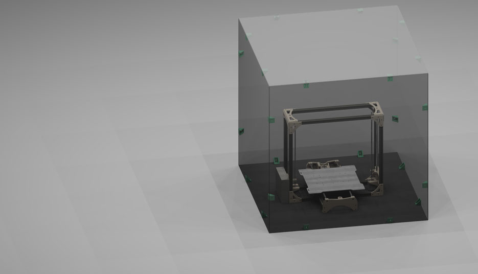
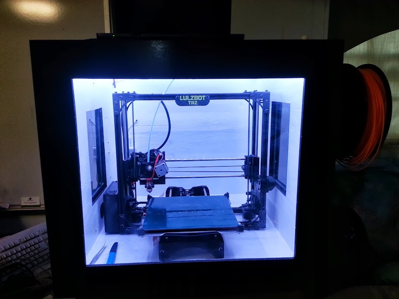
Lastly are enclosure forms and materials. I like user:1013’s simple cardboard enclosure. But if I want to have a webcam filming the printing so I can playback later and figure out where things went wrong, then I need light. If I want the process to be visible and not have to open and close the cardboard enclosure to see, I think the material needs to be transparent or have transparent windows. If I do window openings like user:benfarmer, how much extra labor does it add to cut out the windows and cut glass and wood. Granted if the wood is free materials sitting around, that is a different story. I like the idea of a Plexiglas enclosure, no windows to cut for viewing. One material could create the entire enclosure. Downside, scratches and dirt make it harder to see through and clean plastic enclosures, glass would be better for visibility but not for durability. Also, does the enclosure even need a base? Or can we just create an enclosure lid we set over the entire printer? Similar to something you set over a cake or pie. Three 3’ x 6’ sheets of Plexiglas, 3mm in thickness, might run you $150 total and could each be cut in half and attached with printed corner braces and create the 6 or 5 sided enclosure we need. How about a door though to get in and remove your print? How about no door? Connect two neighbor sides and the ceiling as the removable section of the enclosure; the other two neighboring sides and the floor are stationary. Now you have access to the electronics without pulling the machine in and out (to replace blown fuses) and access to the front of the printbed. More access area then if you had one door on one side. See picture for example. The image is to scale, so you see a 3’ x 6’ sheet of Plexiglas cut in half is still way too big, and I said I want to keep my foot print as small as possible. So I still need to find different size sheets that would create a small footprint with the least number of cuts needed. Oh, and we’ll need handles to lift the enclosure on and off. Oh, and not sure a 3mm piece of Plexiglas is strong enough to lift the entire printer and enclosure. Oh, and we’ll need access holes to bring the power cable in from the power supply and a USB cord.
I think it will be great when I finally get the printer and I am too busy tinkering with it to sit and write these long posts. I like to write out the thought process though so others can see what I’m considering and maybe catch things I’m not even aware of. Hope it sparks some ideas though, and hopefully others can improve on my ideas. I’ll definitely post my enclosure when it is all said and done.


 ) for the release of it I plan to make the full design and capabilities open to the public. For now what I will say is it will cost anyone building it probably $400 + to build and should last a lifetime.