Or your Mini-Rambo sees the Y min switch as closed and is running it forward to get off it. If your belt is routed correctly you may have lost the RAMBo or have a short to/in the print head.
From a top down view the bottom picture matches . however that is how it is supposed to go as the plastic belt piece has three holes and it can only be mounted one way. The grooves in the plastic match the grooves in the belt and it matches the ohai build documentation. And im confident the build plate isnt backwards compared to the ohai documentation. I can take a picture tomorrow.
The print head (extruder) is not connected yet. Would that make a difference??
Motor could be plugged in backwards too. Or you may just end up having to flip the firmware switch
If you have not updated the firmware, you probably still have the default Ultimachine firmware on the Mini-RAMBo. Which will not work correctly, so you need to re-flash it to the mini firmware.
Okay, so i updated the firmware. It didn’t seem to help. So i tried switching the limit switches. I guess that worked. So i am going to assume i just had the max and min directions confused. I could not find any good diagrams for direction except this one which is not for a lulzbot machine, so apparently this diagram is NOT accurate for the lulzbot mini?. So apparently the bottom left corner is not HOME like it is on nearly all CNC machines?? If so, than that’s a little bizarre.
Can someone help me with the correct min and max locations so i dont screw up the x or z axis? When homing Z i think it goes up so i guess the top would be z min then?
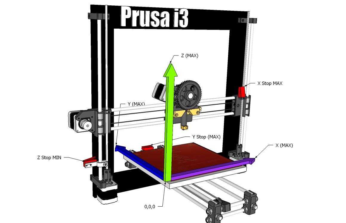
Nope! The top is Z MAX.
Nope! The top is Z MAX.
It homes to Z Max, X Min, Y Min. Or X0,Y0,Z158.
Ok. What about the x-axis and y-axis. which direction is min and which is max?
because currently my machine is moving the bed plate away from me when i try to home the y-axis. After switching the y-axis limit switches i assume the direction toward the motor is y home.
Yes, left is X min, and back is Y min.
I’ve got the extruder mounted since the last photos. And almost everything wired up. I think the last mechanical part i need is the plastic cooling fan mount which also houses a limit switch. Other than that just waiting for a few electrical parts. Hope to have this whole thing finished and working by next week.
The only thing i can’t seem to find is the micro blower fan. And the Lulzbot site is out of stock. Anyone know where i can find one? Even better if someone likes my project and is willing to donate me one for free  , but i wont hold my breath for that one. Apparently it’s a pretty critical part as without it the filament can melt too early and clog the extruder.
I might just happen to have a spare one laying around…
Okay. Everything is nearly ready. Everything is assembled and wired up. Now i just need that micro blower fan and to wire up those little fans and the x-axis limit switches and i’ll be ready to test. I do need a few countersunk M3 screws for the bed leveling washers, but that’s about it.
Check Ace hardware in Orchards, they have a wide selection of metric hardware parts for some reason. 
Thanks. There is an ACE nearby that i can run to if need be. there is also another local lumber store that carries some metric screws, so they might have some to. I’l worry about that once i get the micro fan. Hoping it will arrive tomorrow.
Today i printed out the last set of connectors for my IGUS chain as i mistakenly ordered only two instead of three. So i made my own. The colors clash a bit, but whatever. Right now functionality takes priority over aesthetics. I’ll probably print a black one out at some point when i have black filament.


First printing photos:
I’ve solved all major issues with my DIY homebuilt Lulzbot Mini. I fixed the bed leveling issue for the most part, although my printer has still been starting too close to the bed when starting and the filament is unable to get out. I “fixed” this issue for now by placing some extra washers to increase space between the washers and the bed. I also fixed that very bizarre geometry issue where nearly every print was printing way off center and off to the left and other crazy skirt behavior. It turns out i needed to connect my ferrite toroids to eliminate electrical interference. I honestly thought i had a bad board, but that was the only thing i hadn’t tried.
This is the first time i’ve used PLA, so i’m not sure if the minor issues are from this printer or if that’s standard PLA fiddling. Printing has a few hiccups. Mostly the PLA coming off the bed mid print, even some warping this last time. Not sure if that means i should try the gluestick method or turn the fan off for the whole print. But anyway those are print issues not related to hardware as far as i know. changing the heat settings to 220 seems to help the PLA come out at a more constant rate. Perhaps the esun filament is just not even diameter?
The good news is that it now works enough that i can now print test pieces! The first object i printed was the example / logo from OpenScad. Once this thing is working better (if that’s possible) i will print out the octopus that the Lulzbot printers ship with just for kicks. Do factory made Lulzbot printers come fine-tuned? Is there a way to fine-tune mine without reflashing some custom firmware?
(P.s. If a forum mod wants to move this thread to the photos area i don’t mind. Whichever part of the forum is best. Otherwise i guess it can stay here.)
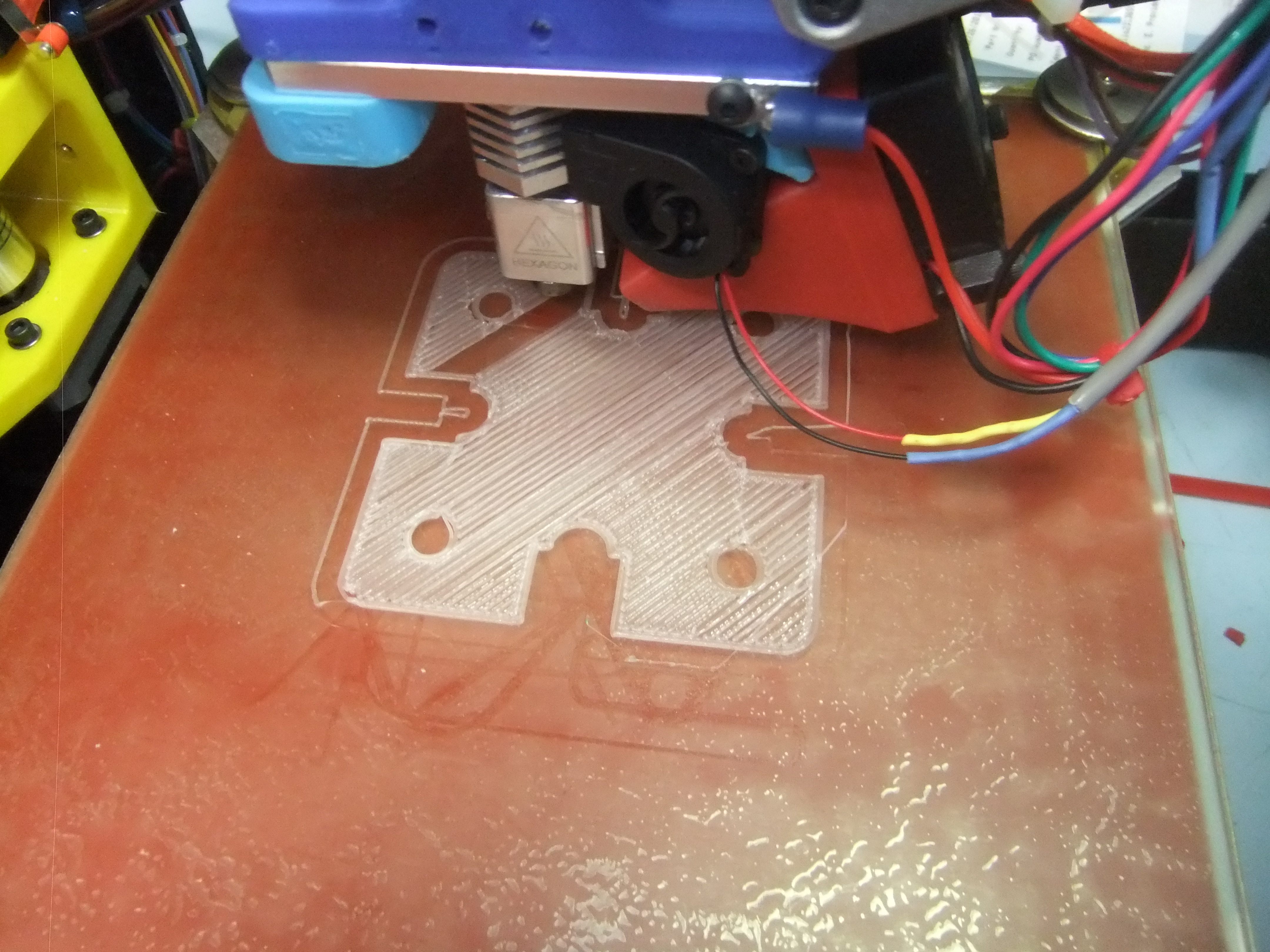
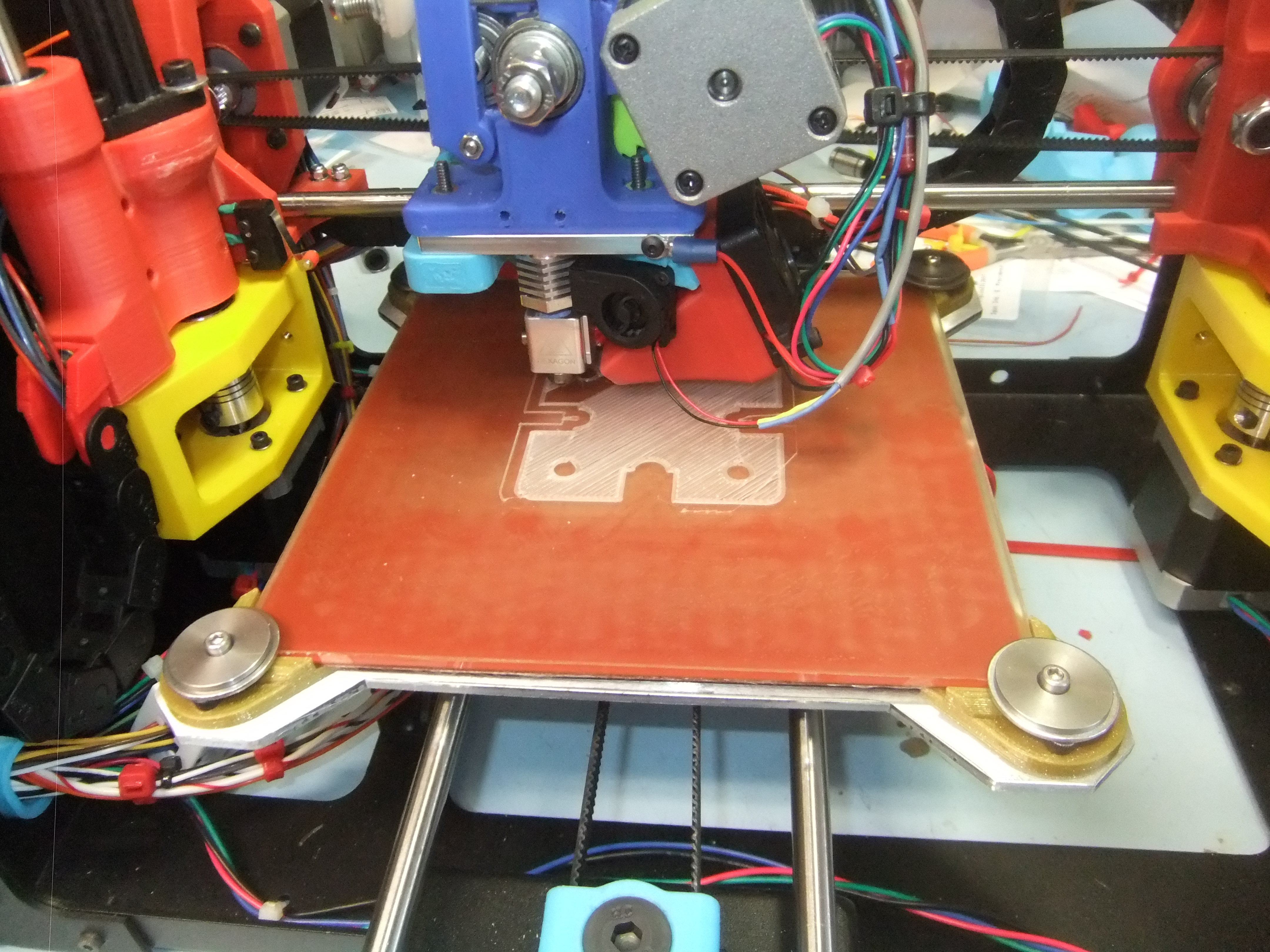

If your tool heas is starting too close to the bed, there is a gcode setting you can change to adjust the z-offset. Most Minis have a negative z-offset (since “zero” is at the top of the washers once the auto-leveling sequence is complete - it’s a it more complicated than that in actuality, since it calculates a surface based on all four washers). My mini came with the z-offset set at -1.32. That was a bit too close to the bed, so I adjusted it upward (i.e. in the positive direction) to -1.22.
Here’s a link to a post describing how to adjust the z-offset using G-codes. That’s the method I used.
You can also change it via a setting in Cura, if that is what you are printing with. Go to Machine-> Machine Settings… Then enter a value in the “Z-offset (mm)” box. I’m told this software setting just adds or subtracts to the z-offset stored in the Mini, so if you want to move up by 0.1mm, you’d just enter 0.1 in the box (or a negative number to move down). I have not used this method of setting myself, however.
The Cura method does seem like a quick way to make changes while getting dialed in, but the setting doesn’t carry over if you print with some other software, or change to another computer to control the Mini. If I were using this to fine-tune, once I had it figured out, I’d make the appropriate adjustment via the first method, and reset the Cura software to 0, just so I’d know I had it stored in the Mini.
Looks great Biolumo! I am curious how much did it end up costing?
honestly i haven’t added it all up. With shipping and certain things bought for a higher price than what lulzbot can get in large quantity discounts (and my experimenting with bearings, etc) i would guess that i ended up in the $900-$1000 range. If that’s true then i was able to save some money (which has or will be spent on filament and the raspberry pi). However even though price cost was one reason to do this project (the other being that i would gain valuable experience and knowledge of every part of how my printer works) i honestly would not recommend the process as there were more frustrations than i had hoped there would be. The quality that one would get from Lulzbot / A.O. & the warranty is worth the extra money in my opinion. If you want to do it for the experience then sure. If you want to do it for the money i say rethink your motivations. Not that it can’t be done cheaper, mind you. Part of that extra cost was because i was somewhat doing this all in the dark with sketchy build instructions and low knowledge of parts going in. If i were to do it again i could probably make wiser decisions, but i don’t know if i will or not. One potential place to save money is by using linear ball bearings instead of the igus ones. I made modified parts to fit these on Thingiverse and i’m currently using a few on my machine right now. The downside is that the steel rods are rather soft and the ball bearings make scratches on them if you don’t replace them with hardened steel.
I’ve been very busy until of late. My mini still isnt where i’d like it when starting the prints. I haven’t tried the z offset yet, but when i do i would like that information stored in the firmware for everytime. So are you saying that i can save this in firmware by using the cura advanced settings and just resetting the value to 0? Has anyone done this before on their mini? I noticed the new Lulzbot Taz 6’s have a nice z-offset adjustment on the fly using the fancy LCD screen.
Biolumo,
Are you running Ninjaflex corners or are those from a 3rd party printer?
The link I posted about setting the z-offset using G-codes will store it in firmware (if you use the g-code to store the setting). So if you used the Cura advanced settings, and got things right where you want them, just add the present z-offset number stored in the firmware to the number you have in Cura, and store that result using the g-codes, and set your advanced setting to zero. For example if whats stored in the firmware is -1.32 and you have 0.1 in your advanced settings, that will give you the same result as using -1.22 and 0.
The school I’ve been volunteering with has only used PLA so far. We’ve got that fairly well dialed in. If we find that the HIPS we’re going to next (when the current PLA is used up) needs a different z-offset, we may just bump the advanced setting to dial that in. Once we know we’ve got it, we’ll probably store the setting for whatever filament we are likely to use most often in firmware, and just adjust the others from the advanced settings. I’m less worried about someone accidentally screwing things up by monkeying with the advanced settings dialog box than by typing in G-codes.