I bought two TAZ 4’s and one of them always printed the 1st layer much thinner in the center of the bed compared to the four corners. This occurred after utilizing the stock four corner clips to level the print surface as prescribed by Lulzbot. At first I thought this was due to the 10mm x-axis smooth rods bending under the weight of the extruder. I dispelled this hypothesis when I installed the bowden style version of the e3d cyclops hot end to the x-axis which substantially reduced the weight on the x-axis, but did nothing to get rid of the thin 1st layer in the center of the bed.
This led me to believe that the bed must be bulging in the center instead of the x-axis drooping. At this point I suspected that leveling the glass bed utilizing the four corner clips as prescribed by Lulzbot was over constraining the glass causing it to bulge in the center (this turned out to be true). I upgraded my TAZ 4 to the TAZ 6 x, y and z axis upgrades including the auto bed leveling hoping this would somehow fix things with all the fancy improvements the upgrades would bring. Instead of a bulge in the center of the bed I now had a saddle shaped bed where the front left / back right corners printed thinner and the back left / front right corners printed thicker. To illustrate this see pic 1 showing a calibration print and pic 2 showing a close up of the thin front left corner. Both pics show the 1st layer because that’s when thin spots are most visible.


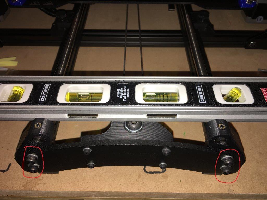
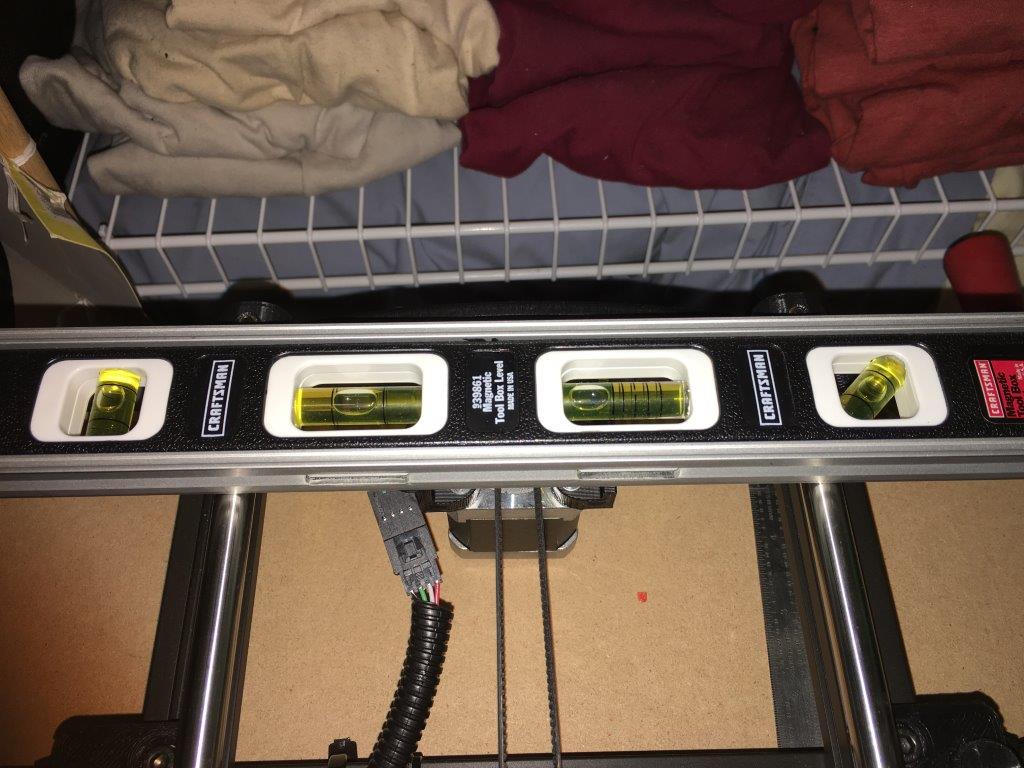
Now I was onto something. I checked the levelness of the two y smooth rods against each other (see pic 3 and pic 5) and found that the back of the right smooth rod was low. I unscrewed the four Y axis idler installation screws (circled in pic 3) and four Y axis motor assembly installation screws (opposite side of pic 3). Next I unscrewed the thumb screws that secure the Y axis to the TAZ frame (pic 4). Now the Y axis was relaxed enough for me to try to level it properly.

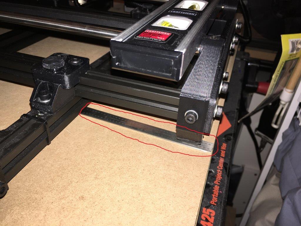
I had to stack two metal rulers under the back right foot of the Y axis to level the two Y rods to each other (see pic 6). The two metal rulers raised the back right side of the Y axis 0.96 mm.
Now I tightened everything back up. Alas, this did the trick. I finally leveled my bed. The first layer is now going down beautifully in all four corners and in the center of the bed. As an example Pic 7 in my post below shows the front left corner and Pic 8 shows the front right corner after performing the Y rod leveling trick. Only 6 pics are allowed per post; hence the reason for these pics going to a second post. I measured the first layer across the entire calibration print and found only a 0.06 mm difference which means the entire print bed is now level to within 0.06 mm. This is plenty good for the 0.2 mm layer heights I typically print.
Pic 9 below shows how nice the entire calibration print now looks.
I could probably dial it in further by getting a digital level, etc, but no need to spend time on something that won’t make a difference in the quality of my prints. I’d rather spend time making cool prints.
Thoughts: Lulzbot should make it a point to include leveling the Y rods against each other in the assembly instructions. Y axis adjustable height corners / legs would be very helpful in accomplishing this step.


