Hi All, I have drawn an object on Tinkercad and am trying to print it. At one edge of the shape is a large radius curve. This prints as a straight line with a bump in the middle. It does it consistently on all layers, several attempts. The bump is not evident on the Tinkercad model, the .stl or on the slicer. I figure it is some sort of artefact caused by step size of the stepper motors. Does anyone know what the actual cause is, or how to fix it? Lulzbot TAZ 5, Cura Lulzbot edition 3.6.20. I have photos and files if we can figure how to upload them.
The description isn’t helping much. You can just do the share link feature in tinkercad to show the files, which may help, but photos of the problem areas is also necessary.
Step size on the motors is rarely any cause for noticeable defects.
Hi Wrathernaut, thanks for the response. Link to Tinkercad is here:
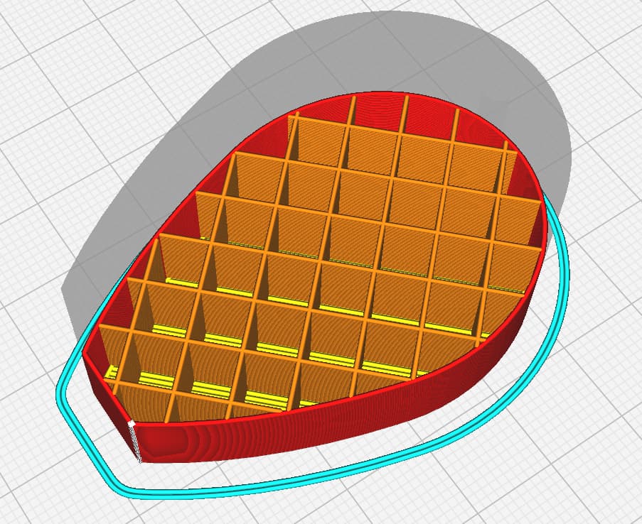
Screen shots of the Cura layer and photo of the resulting object below.

Looks like you’re printing too close to the bed.
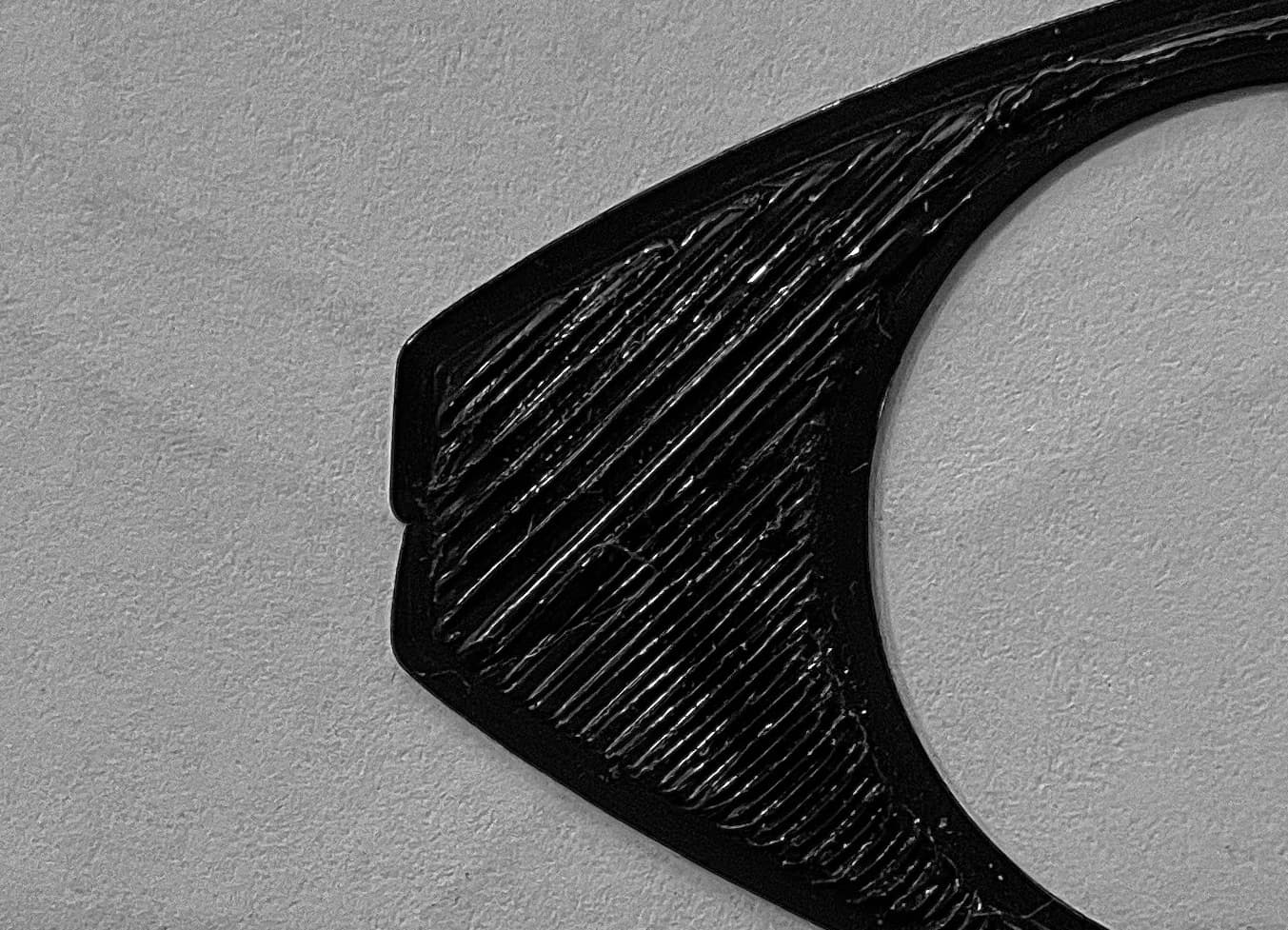
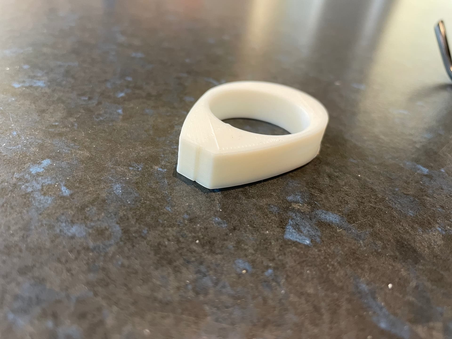
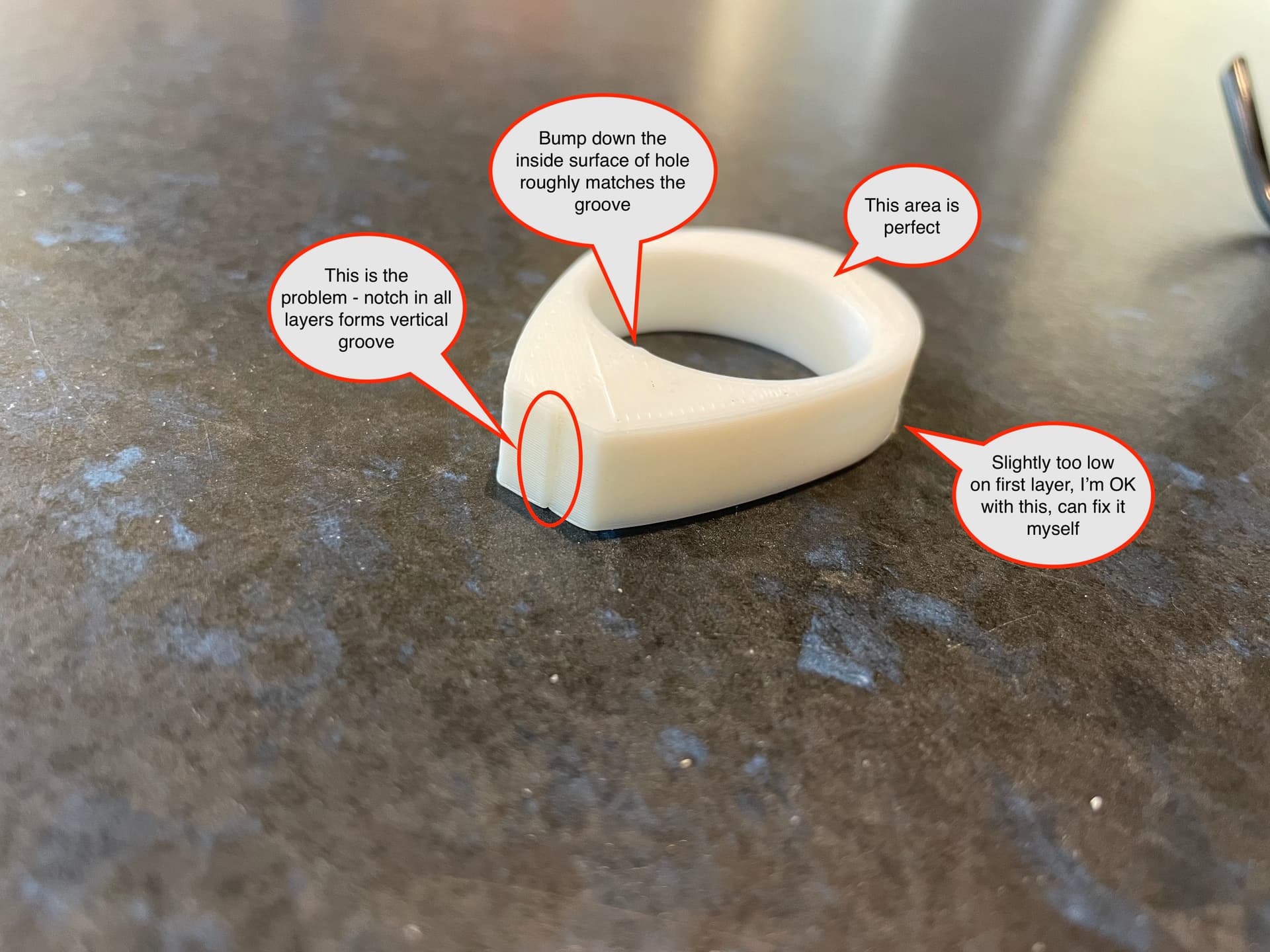
Yes I know there is a slight elephant foot but I know how to fix that. The notch problem is separate issue. It persists across all layers. See below photo of one I printed to 10mm high. The notch forms a vertical groove. There is a corresponding vertical ridge on the inside of the circular hole, you can just see it on the top layer in this photo. It is less than half the depth of the notch in the left end and not evident on the interrupted first layer but it becomes visible when the print is a few mm high.
I thought at first it might be backlash - free play in either X or Y belts. However, belt tension is OK according to setup directions. Also there is no notch at the other side of the circular hole or outside of the shape on that end (big end of the egg shape). Those areas print perfectly. I have printed several other items in between attempts at this one and they are all fine too.
I will try rotating it 90 degrees on the bed tomorrow, then try Random Z-seam (it was Sharpest Corner), and see if anything changes. But in the meanwhile, any ideas would be appreciated.
If your z probe offset is perfect and you still get those ridges on the first layer, overextrusion is usually the problem. That can be from slightly oversized filament or improper e steps set too high. It could also be caused by trying to do a very small layer height with thicker lines.
Thanks for your interest but I fear we may be speaking at cross purposes. Ridges on the first layer aren’t the problem I need help with. The problem is the left end of the object appears as a straight line on the model and on the slicer tool path but prints with a notch every time, in all layers. I have annotated the pictures as best I can to clarify this.
The screen shot of the slicer shows first layer and the black filament print pictured is first layer only because I saw the problem and stopped the print. However, it is the same on all layers - tool path shown on slicer is straight, print has a notch indented to the right in the X direction. On the finished object this shows as a vertical groove which is unsightly.
I have tried rotating the object on the build plate but no matter what orientation the notch is always there exactly the same location on the object (small end of the egg). eg. if I rotate it 90 degrees A/C the notch is in the same location on the object (small end of the egg) but now in the Y direction, similar result at intermediate angles.
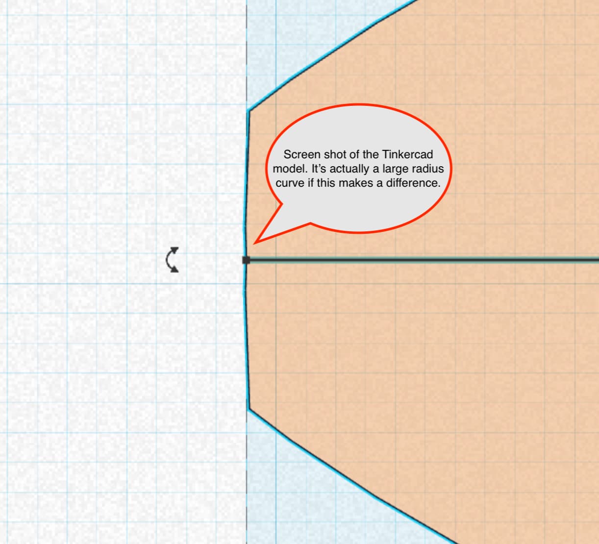
The straight line is actually a large radius curve if this makes a difference. I will try making it absolutely straight. However, I have never had any problem with large radius before and I can’t imagine why it does this. If I get desperate I will fill the groove with car body filler, sand and paint it, but I would like to get to the bottom of the problem. There must be a reason.


Ok, that helps explain it.
Is that ridge where the layer is starting? You can try and move the layer start position to put it closer to an inside corner, or even just try using PrusaSlicer to get even more control over layer start positions.
Changing your retract on layer change setting is worth giving a try as well.
1 Like
It’s not the start or Z step point, those are inside the circular hole (logical place to put them). I figured it may be a problem with the model or its interaction with the slicer so I changed the short end from 200mm radius to straight. This solved the problem at that end but now I have a vertical ridge on the long side (near where it says “Slightly too low…”). Again, the lines look perfect on the tool path but there’s a dent on every layer including the skirt. There is no logical explanation for this and it doesn’t happen on other models so I assume the software hates me. I will next see if I can download another slicer. Note I have a part that functions satisfactorily and I can sand the ridge. Solving this is now more a point of honour.
The tinkercad link doesn’t work anymore. I was going to give a try here, if you want to re-post the link, or the STL.
I’m really curious how you resolve this, that is really interesting how you got such a missing artifact from your model and slice.
Here is the link to the latest version. The vertical fault now appears on the outside near thinnest section.
The interesting thing is not just the error but that it doesn’t appear on the tool path! Does this mean that the tool path is an “interpretation” from the G-code?
I’m leaning toward mechanical issue - like a loose grub screw on the X axis or loose belt? Could be an extreme form of ringing? I’ll do a quick print today and see what comes of it.
Tinkercad is still throwing an error.

Are you doing a share link, or just the address when you have the file open?
I made it Viewable / Discoverable. I thought if I sent a link it would work anyway but hopefully this helps.
Cura 5.3 has other issues with the model:
Inspection shows there’s a weird spot in there from filling in:
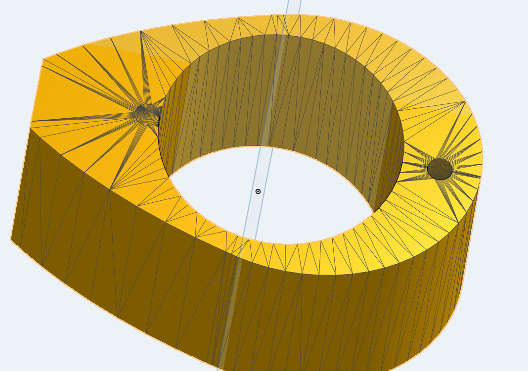
I don’t think it would cause the error you’ve seeing though, but it is confusing slicers, so I can’t discount it as being a potential source of confusion. I think it’s still coming down to something mechanical on your printer.
Was the model made by mirroring halves?
It was mirrored on long axis but I layered another shape over the joint area. The back edge is where the ridge was originally so yes, potential cause. However, that edge was a large radius curve. I thought it may be a cause so I sun straight across the back. The ridge is now at the side (thin section between inner circular hole and outer egg shape).
The most confusing thing is that it doesn’t appear on the slicer tool path but appears on every print, regardless of location or orientation of the part on the build plate so I think this excludes a mechanical problem. I can see the stepper motors move as it hits the area.
Thanks for checking. The anomaly you showed doesn’t appear on Tinkercad so it may be a Tinkercad artefact confusing the slicer. I think it may be easier to redraw the thing from first principles, maybe taking a different approach, and see if that helps.
Re mechanical problems: The ridge is always in the same place on the object, regardless of location or orientation on the build plate so it isn’t related to any one movement axis. Not sure what I should be looking for but the printer is misbehaving in other ways so it’s about to get an overhaul. That may fix it too.