I’ve been using the TAZ6 for over a year, so far, working wonderfully. But now the bed doesn’t heat, and troubleshooting is a real doozie. Neither LulzBot support staff nor I have been able to figure out what is going on.
Most recently, when I tried to print, the bed wouldn’t heat up, so the print wouldn’t begin because it was waiting for the bed to come up to temperature. When I lower the temperature manually, it will continue the print. Raising the temperature manually, or via a print job doesn’t work.
Things I’ve measured/tried:
THERMISTOR
The display shows a reasonable temperature measurement (26C)
The displayed temperature is responsive (can heat the thermistor and 26C increases as expected)
Thermistor reads 95kOhms
I think I can safely say the thermistor and its wiring are not the problem
HEATER
Reads 1.9 Ohms
Seems appropriate
Just to be sure, I replaced the bed assembly, no change
I think I can safely say that the bed assembly isn’t the problem
RAMBo
The F4 (15A automotive fuse) still has continuity
The Mosfet seems to be in good shape
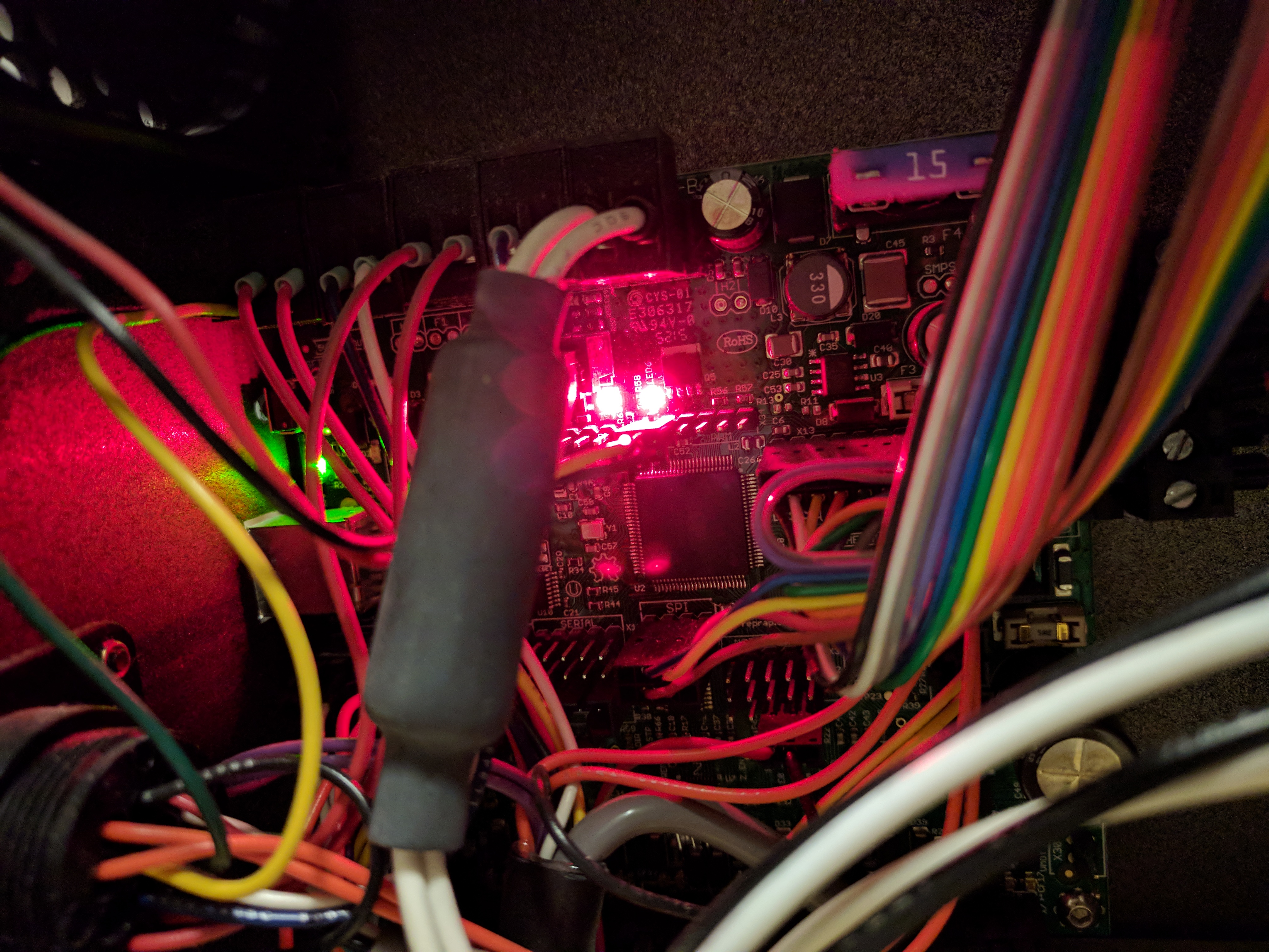
The red blinky light is working, which I think is supposed to mean that the bed heater should be getting power
HEATER WIRING
I get 18-22V at the heater connector
If I connect one side of the heater connector (don’t complete the circuit), I read 18-22V from the heater side of the connector to the open side of the connector coming from the RAMBo. This works on both sides. So I think the connections are ok.
When I complete the connection and plug both heater connectors into the cable, the voltage drops to 10mV, practically 0.
This makes me feel like the board is able to source the voltage, but wimps out as soon as there is any current draw. That makes me think it might be the Mosfet in some fugue state where it isn’t totally busted, but somehow is providing voltage, but gives up as soon as there is a current draw… But not sure.
Any thoughts on this mystery? Should I replace the Mosfet? With which one? Or do I need to plop down the $220 for a new RAMBo (or buy a new one cheaper somewhere else since I don’t need the connector kit - recommendations?)
Thank you so much for your help kmanley57 and piercet! I finally figured it out!
I replaced the RAMBo and after examining the old one, I found that the right pin for the heater wire was melted off of the RAMBo. Pretty scary/surprising stuff. It’s possible to fix, but just wanted to add this info for those of you looking for solutions at home.
Thank you for all of your help. Pictures below for the curious.
Note the long pin on the right of the long black connector - it is marginally melted off the board.
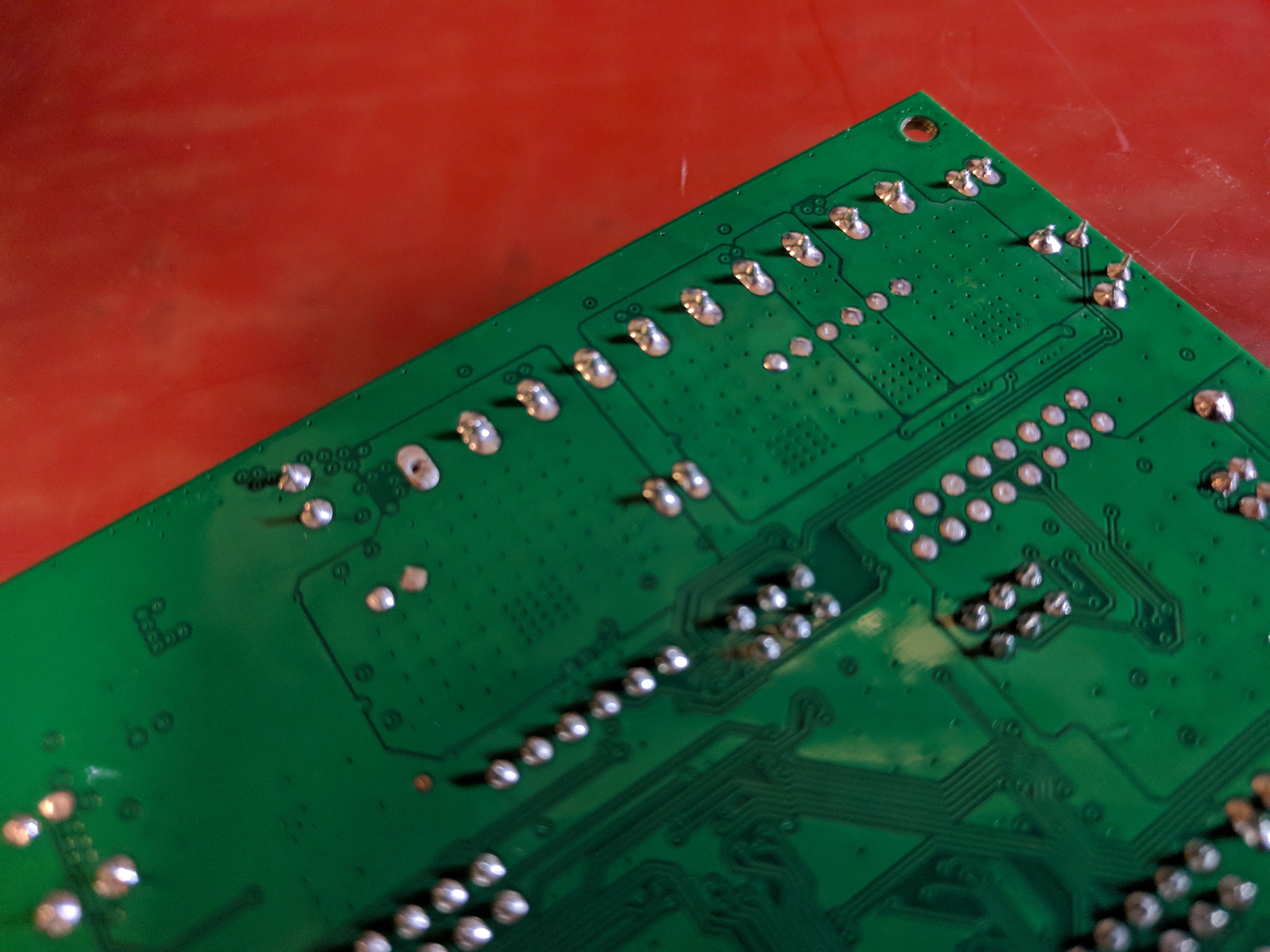
From the back you can see the solder has been melted on the leftmost solder pad in the line of through-hole connectors for the black connector. Crazy that those pins get that hot. Perhard the connection was just not quite good enough and heating up with all of that current passing through?
If the blinking L.E.D. goes out when you plug in the heat bed then the F.E.T. if not then your wiring to the bed. The ~0 volts when plugged in says the ground side of the bed wiring is working, but the 24 volt side is not.
The light keeps blinking when when the bed is plugged in, so i guess the mosfet is okay.
Sorry for not describing the voltage check on the heater connector at the bed well enough. Here’s what I did:
Measure the voltage across the connector coming from the controller, reads ~20V. That means the controller is supplying voltage. Good.
Connect the positive side of the connector coming from the controller to one of the leads for the bed heater. Measure the voltage from the open ground on the controller side of the connector (not connected) to the positive connector on the bed side of the connection (connected), reads ~20V. That means the positive connector is good. Good…
Disconnect the positive connector and instead connect the ground side of the connector coming from the controller to one of the leads for the bed heater. Measure the voltage from the ground on the bed side of the connector (connected) to the open positive connector on the bed side of the connection (not connected), reads ~20V. That means the ground connector is good. Good! That means that everything should work! But it doesn’t. And when I…
Connect both the positive and the ground and measure the voltage between the two on the bed side of the connector (all connected now), the multimeter reads ~10mV. I’m a little perplexed at why that would happen… unless the power electronics were having trouble supplying current, or if there were large resistances somewhere else in the system.
Any idea what the issue might be or where I made a mistake diagnosing?
Grr. That would be frustrating to debug indeed… In my testing, I have tried to control for intermittent contacts (hence the plugging in each connector separately to ensure I’m still getting voltage). And that didn’t seem to be the issue. Unfortunately, no other harnesses to try out. But I could purchase them, if that is the most likely culprit in your opinion. It will just set me back a few days.
Do you think it could have something to do with the voltage bouncing around between 18V-22V? Is that normal?
The voltage bounce is probably normal, since it’s tied to the thermistor and it may be trying to heat in shorter increments so as to not burn a wire. that or the thermistor is detecting a change in ambient heat and dropping the heat voltage a bit. Or, it could be a short.
For a PWM circuit it just might be. Since it is a pulsed voltage going to the heat bed.
As for checking the wires/heat bed just measure between the two connector pins that plug into the RAMBo board (unplugged from the board of course.). It should read around 2-3 ohms. That checks both of the wires and the heat bed at the same time. Then if that measured bad check each wire and the bed separately. Measure the voltages between the wires and the chassis to check which wire is broken. You have to use a known reference point. and the chassis is a known grounding point that you use to check voltages from. So measure the voltages on the bed connector from the chassis to each wire not between each wire. One wire should read ~20 to the chassis and the other should read ~0 volts to the chassis.
But it sounds like you just are not getting the power to the bed. (Wires) The L.E.D. would go out if the F.E.T. was not working right. The L.E.D. is across the output of the FET, so if you connect the bed and read ~0 volts and the L.E.D. is still lit then you have a bad bed wire somewhere between the control board and the bed. If you read ~0 volts that would say the ground side of the bed maybe OK. You will read voltage with a high resistance wire(AKA - broken wire that just touches enough) but get no current flow(AKA - no heating). which is what you are describing.
Dude, kmanley57, great suggestion. This is really helpful. I checked the voltages of the wires vs the metal bed-leveling tabs, and sure enough, I get 24.15V steady on one lead and a voltage that bounces around between 3-5V on the other. I think I have found a good lead to start chasing (pun serendipitous). Thank you! I’ll let you know what I find…
So, interestingly, I expected the ground (bouncing between 3-5V) to just be a bad connection, but when I connect the bed (reading 1.8 Ohms), the voltage on both pins drops and begins bouncing between 3-5V. Anticipating that the ground wire had a faulty connection, I expected both connectors to go up to 24.15V and sit there… Super strange. It makes me think again that something on the RAMBo freaks out as soon as it tries to pull current…
I rang the wires separately all the way from the bed to the RAMBo and connectivity was good on both. I also checked the voltage on the RAMBo for the bed heater terminals, and sure enough, it is around 20V when the bed is unplugged and drops down to 12mV when the bed is plugged in, exactly what I see on the bed. Must be a RAMBo HW issue. The only thing I can think of is a partial failure of the MOSFET.
I’d try replacing the two smaller fuses and the large auto fuse too. they may have continuity but only partially? Long shot and probably not it, but it’s only $3 worth of parts and then you have a spare set.
If the voltage drops when the bed is trying to heat, then measure the two metal pins on the top of the 15 amp fuse in the control box. If you find the voltage on both sides of the fuse drops, then you have an issue with the power supply wires coming from the power supply to the RAMBo connector or the supply itself has an issue delivering the current needed. Measuring from the Chassis to the pins of course.
Thanks again for your help, kmanly57 & piercet - I checked the fuses, all has tiny resistances <1ohm and tiny voltage differences when on of <1mV. So, I think they aren’t the problem. The 15A fuse read 24.15V on both sides when measured, which seems good (I assume the fuse is on the positive leg). The problem seems to be on the ground leg, on the connector too, so must be that side. I think I’m going to order a new RAMBo - thanks for the supplier suggestion, piercet! But I still would love to fix this and get this up and running before then.
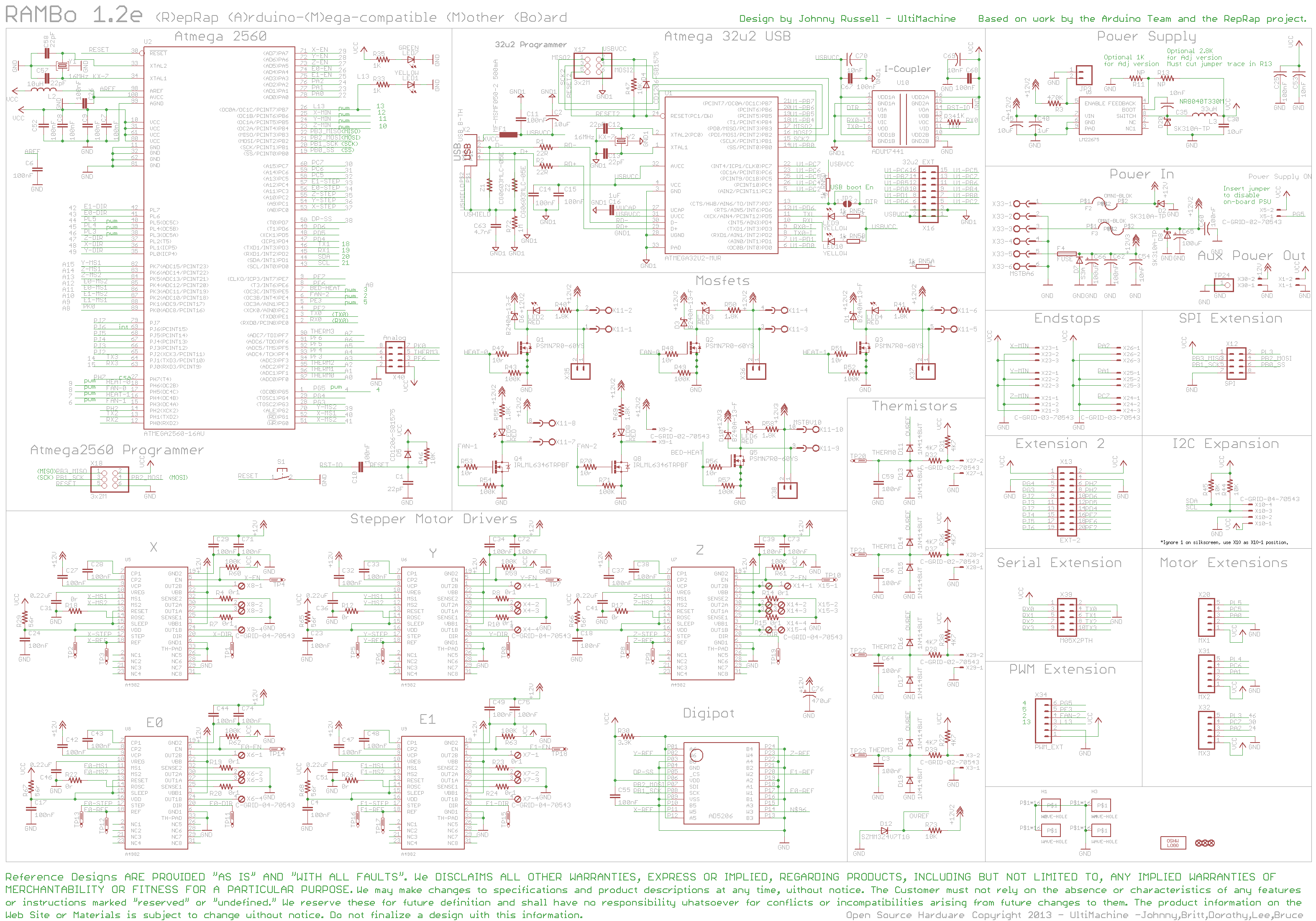
Still the only thing I can imagine is the mosfet having gotten partially fried and loosing the isolation between ground and source or sink… Do you guys know which mosfet that is, or even better, have you ever tried to replace it? It seems like the mosfet isn’t an uncommon point of failure, so it would be nice if it were connectorized for fast swapping…
Here’s the Schematic for the Rambo 1.3 board Rambo v1.3 - RepRap If I’m reading this right it’s the one labled X-38. Never tried replacing ones. Resoldier skills are not my strong suite heh.
Replacing the F.E.T. is going to be a chore! It has a substrate tab under it that is used as a heat sink to the board, so you will have to flow the fresh solder under the part before soldering the pins down. If you do not have the correct SMT soldering device you may not succeed.
Well, I ordered the RAMBo, but it hasn’t come in yet. I couldn’t wait (and I was planning on throwing away this ROMBo anyway, so I went ahead and replaced the mosfet with my handy dandy soldering iron, and somehow did it successfully! Didn’t break anything, and the red LED for the heater still blinks on!
Unfortunately, the bed still doesn’t heat. Flaming bags of poop. I’m going to try bypassing all of the heating wires and see if that helps - at this point, fresh out of ideas… Hopefully the double-bypass surgery goes well…
Well, shyoooooot. I just bipassed everything from the RAMBo Connector to the bed, and still the same story - 20V when disconnected, but as soon as the bed is connected, the voltage drops to 10-15mV and the bed doesn’t heat… Must be on the RAMBo, but isn’t the mosfet… Well, hopefully the new RAMBo fixes it. In the meantime, I’ll be looking over the schematic to see if anything else looks like it might be a culprit.
I just had this same problem on my Taz 5… I almost ordered a new RAMBo and/or a MOSFET (fortunately, I have SMT equipment here), but it turned out to be the Lulzbot harness had partially fried. Both sides of this: https://itworks3d.com/product/lulzbot-taz-4-5-bed-wiring-harness/ had fried internally, with very little visible burning outside.
Exactly same problems described here.
I cut the ends off and soldered everything together, and viola, everything is working again just fine.
I’ve heard those harnesses are prone to problems anyway, so… there we go!
Just wanted to chime in, in case anyone ran into a similar issue. Check the harness as well. The wire tested fine with a multimeter, showed voltage, no continuity problems, etc… but when a load was put on it, it just failed.
JoshZ, thank you so much for jumping in and sharing this info. Super helpful, and seems plausible. A lot of contact resistance would definitely cause the issues we saw. I tried bypassing the entire wiring harness from the RAMBo straight to the heater on the bed (a brand new bed), and still nothing. I wonder if the issue could be in the terminals on the RAMBo. Is just seems super unlikely that it would be in the solder on the board… What do you think?


