Hi all, i’m still in need of some help. Still working on my DIY Lulzbot Mini project. What i’m stuck on right now is getting the bed leveling probe to work. I’ve gathered that there are basically 3 limit switches for the Z-axis. One for Z-max (Z home), one for Z-min, and one when the extruder touches the bed leveling washers. It is this last one i’m having trouble with and for the life of me can’t get it to work at all. At the moment i’m assuming i just have a wiring problem, but I’ve tried everything i can think of to solve it.
according to the ohai build instructions for electrical, the picture for step 10 seems to match the wire colors that are used for the Z-probe, however the picture shows that this needs to connect to the Z-min position, which seems to be incorrect as the extra z limit switch position on my mini rambo does not stop the z-axis when triggered, but z-min does. So i am currently under the impression that the lower limit switch does indeed go to z-min.
then in step 12 it shows the extra z limit switch port with blue and black wires. I would assume that this is where the bed probing is triggered despite the colors not matching. However when i test this with either a full print sequence or using the standalone command G30 shorting the two bottom left connectors on the 6-pin connector does not seem to trigger the bed leveling behavior and continues to lower until the z-min limit switch is triggered.
I have even tried the opposite, using the third limit position to see if it is used as z-min and z-min used as the bed level, but that does not seem to work either.
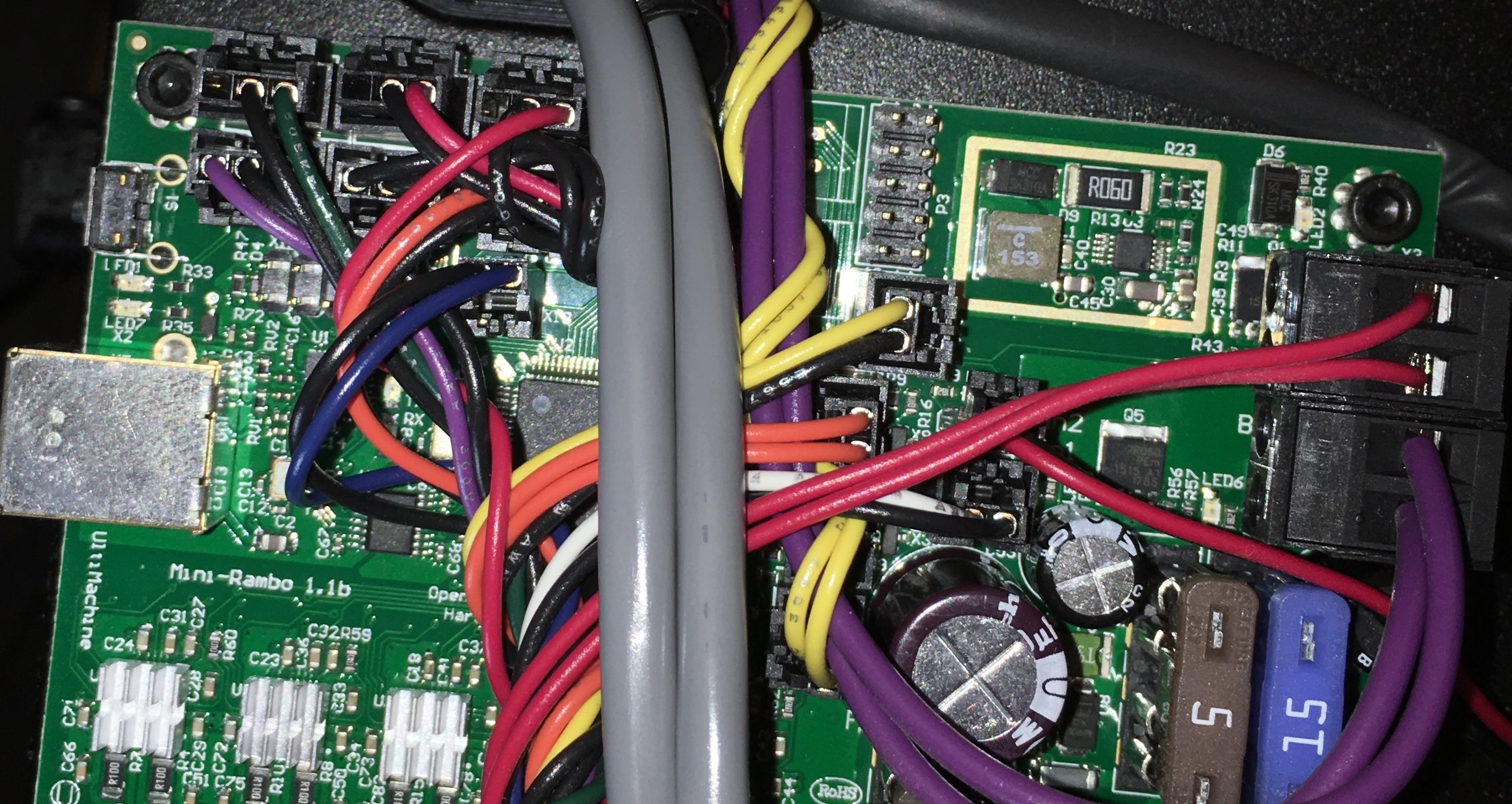
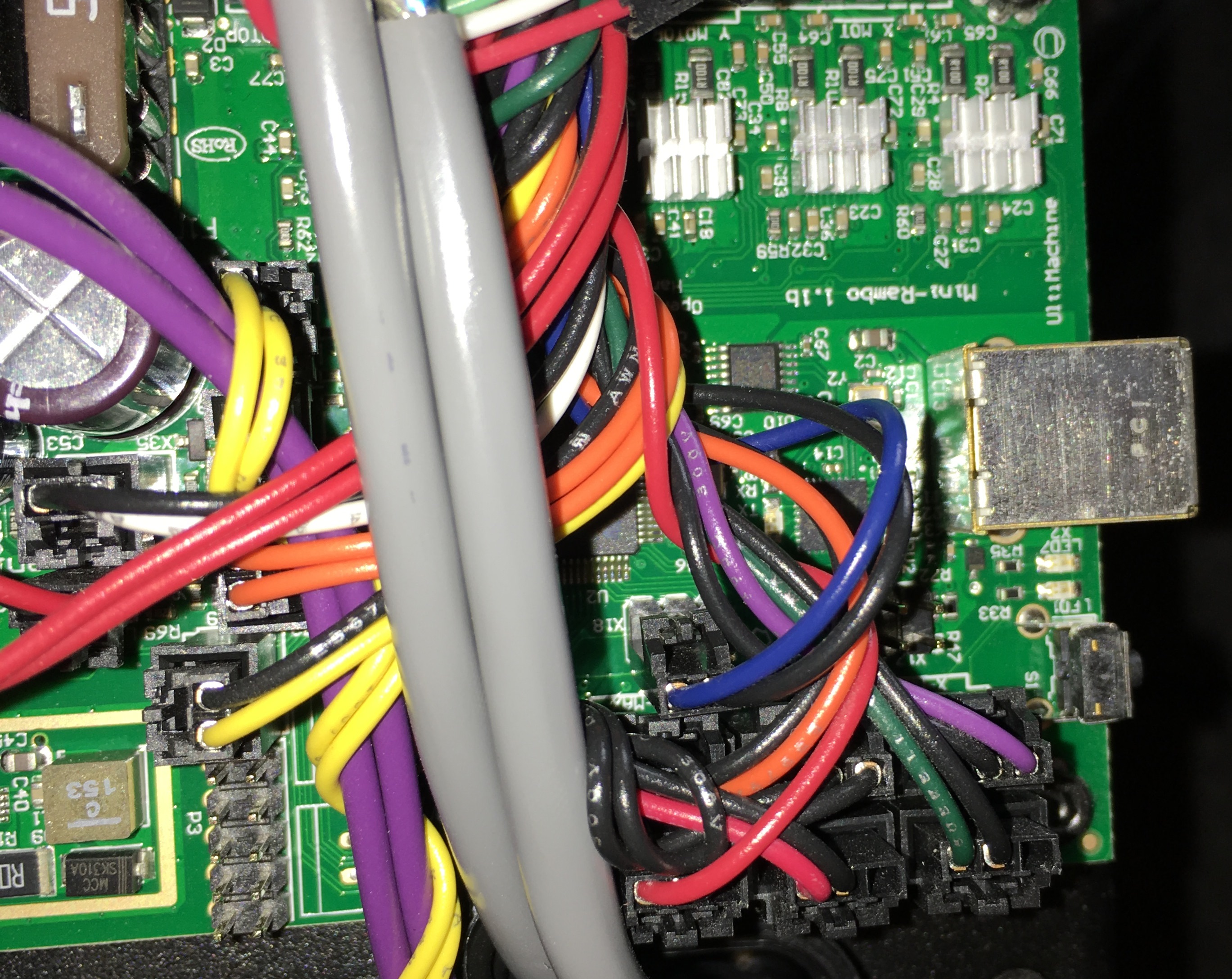
So i’m a bit stumped and could use your help. The most helpful information would be for someone to open up their mini and take a picture of how the 3 z-axis limit switches (the third being an imaginary “switch”) are actually wired. Either i am doing something wrong or my mini rambo is faulty. I can’t seem to find a G or M command that allows me to see when each limit switch is triggered in real-time debugging as that would help too.
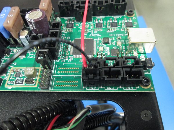
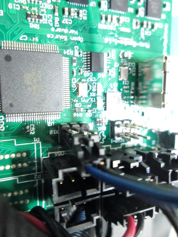
My mini is wired exactly as shown in the OHAI instructions. Specifically, there are Blue and Black wires going to (2) of the pins on the 6-pin header just above Z-Max.
I cannot find any documentation for that connector. It is silkscreened “X18”. Some comments I read, and thinking about how the Mini leveling works, I have to conclude that those two pins are duplicative (parallel) to the (S) and (-) pins of the Z-Min socket.
It is my understanding that shorting those pins (whether manually, or via the nozzle tip touching the build plate washers) should do exactly the same thing as closing the Z-Min switch. The nozzle-to-plate connection is, effectively, just another Z-Min switch in parallel with the physical Z-Min limit switch. G29 looks for closure of the Z-Min limit pins to record bed contact.
Thanks Scott. Those were my thought too, but in testing on mine that’s not what i found to be the case. However it would be nice if someone could test my findings to find out if i am correct. My findings were as follows:
After thinking about this at great length and from testing, i finally had the thought that the way the bed leveling works is that the extruder ground actually REPLACES the z-min switch and that the other limit switch actually does NOTHING. I wired up the extruder ground like step 10 shows to z-min and the bed leveling now works correctly. The downside is that the default lulzbot mini firmware for the mini rambo does not seem programmed to do anything with the other lower z limit switch. In effect there are three limit switches, but only two are functional. This is basically a lulzbot design flaw if i am right. If so there is no real point to that limit switch being there (shown in step 12).
From a safety standpoint however this means that if the extruder nozzle is not clean and cannot make contact with the washers then this could lead to a catastrophic failure with the nozzle crashing into the washers and never stopping. Ideally the other limit switch would be programmed to do the same function as the other z-min, but be put in a place to switch easily if the nozzle goes slightly past where the washer would be so it only bends the aluminum bed very minimally before hitting the backup switch. I am currently considering putting some tape to raise the point where this backup switch will trigger and wiring the two switches together to electrically do the same function since the firmware does not.
If i’m right then lulzbot firmware guys should definitely program that limit switch to mimic the z-min switch and stop the z-axis from moving too far down if pressed.
I agree with your “expectations” about Z-Min. Like you, I would expect the nozzle/washer connection to trigger Z-Min, and if it didn’t, for whatever reason, and continued downward, I would expect the physical micro switch would trigger Z-Min (or better yet, some kind of Error/Abort" condition).
And I’m very surprised that it doesn’t. I did two tests that seem to confirm this, and am left scratching my head as to what that physical Z-Min micro switch does, if anything.
First test, I used the M119 command (show endstop status).
Clicking any of the X or Y micro switches give the appropriate TRIGGERED status
Clicking the Z-Max micro switch gives the appropriate Z-Max TRIGGERED status
Connecting a jumper wire from the nozzle to a washer correctly shows Z-Min as TRIGGERED
Clicking the physical Z-Min micro switch does NOT result in a triggered status for Z-Min (or any other endstop).
Second test, I started the G29 sequence, and while the nozzle was moving down, I manually triggered the Z-Min micro switch. Doing this had NO EFFECT; the nozzle continued to the washer. I did this for all four washers, and the physical Z-Min micro switch had NO EFFECT.
So as far as I can see, the physical Z-Min micro switch is doing nothing – which is the same result you got (per your earlier post, “However when i test this with either a full print sequence or using the standalone command G30 shorting the two bottom left connectors on the 6-pin connector does not seem to trigger the bed leveling behavior and continues to lower until the z-min limit switch is triggered”).
I’m probably missing something here, as I can’t believe AO would install, wire, and connect that physical Z-Min micro switch if it really had no function. But I sure can’t get it to do anything.