Looking at the build documentation for the 6 OHAI: Open Hardware Assembly Instructions and the 5 OHAI: Open Hardware Assembly Instructions and using the Taz_V4_or_5_ONLY_Openbuild_Y_Endplate_Reinforcement_Motor_3_0_E.stl from http://www.thingiverse.com/thing:949082/#files those holes appear to line up correctly. There was an older variant of the file that was incorrectly offset, but the current posted variant appears to be correct per factory specification. Where did you source that file from?
Last week
http://www.thingiverse.com/thing:949082
Openbuilds_v-slot_Y_axis_for_Lulzbot_TAZ_3_4_5_or_6_printers.zip
All files in that archive have a 7/12/2016 3:57AM date stamp.
OK, this is very odd. None of the files in that particular project have been updated for almost a year, and the incorrect older version would have been purged months before that. Can you post a picture of the front of your printer by any chance? Was this a printer sourced directly from Lulzbot, or is there a chance someone put the plates on backwards? It’s either that or there is a revised production run with the plates mirrored from how they were.
That diagram is shown inside face is up (oriented towards center assembled). Note item 5 - Part number stamp specification. This is confirmed as the part numbers are printed and aligned inside the Y assembly.

Got it off amazon to answer your last question about 5 weeks back. The assembly would look like hell if it had the part numbers facing outward…so I’m pretty confident I’m correct.
on the link you posted for the assembly instructions-
https://ohai.lulzbot.com/project/taz-6-y-axis-subassemblies/taz-6/
"Orientation of the end plate is very important, determine the short side and long side of the plate by measuring the distance from the side of the plate to the second set of holes that are parallel to the side of the plate, the short side measures ~65mm, the long side measures ~ 75mm.
With plate laying flat and the short dimension side on the left side orient the Motor mount so its flange is toward the crown of the plate."
The motor plate is installed incorrectly in the tutorial. Short side is pictured on the right. You can tell because the motor mount is hanging down over the arc as pictured in the upper left.
The idler is correctly pictured.
Blake

Assembled w the end plates on backwards. Belt would be straight w the offset reversed.

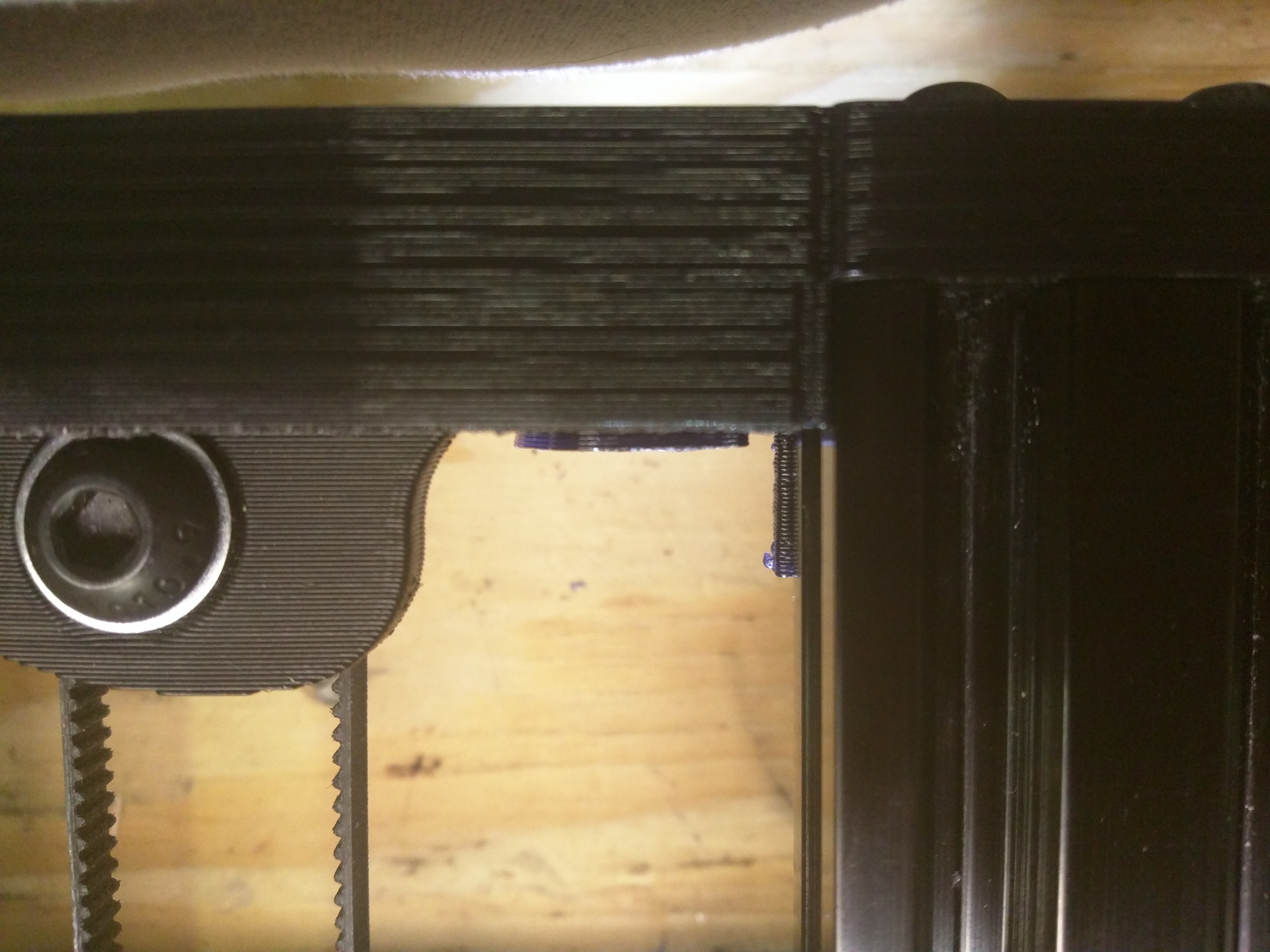
Idler side end stop switch is 4.5mm short of making contact, which is the difference that top center lip sticks out past the face of the stock idler bracket. I like that extra material there to align the rails and its nice having one single part for both ends.
The easiest fix would be getting two bolts 20mm long for the left side of the idler. Print up a small 5mm thick spacer that spans those two bolts. Spacer will be pinned off the top bolt, on the lower bolt put a nut to lock the spacer on.
Would of been amazing if this worked… a 20mm long upper bolt w 2 nuts locked together on the end misses depressing the button on that stop switch by 1.5mm. I’m sure someone makes a huge oversized nut, but my spacer idea would eliminate having to hunt this down.
Last thing i forgot, every program i opened up this end bracket model in filled in these offset holes. The plug was only about 1mm thick, i drilled it out.
I’m gonna run this as is w the stop switch temp rigged up, reprint the corrected endplates and spacer.
The 1mm thick filled in section in the holes is intentional to allow the socket to print correctly. Without that you would get droop in the middle of the screw hole since that part prints bed down. A cylindrical support structure also would have worked there, but they sometimes stick to the sides in narrow holes.
I’ll post a mirrored variant of the end plates tomorrow here, but looking at the documentation the existing part still looks like the correct version to me, and when I test fit the taz 6 bed in the instructions, it fit correctly with good contact on the limit switch. So, I dunno. It’s wierd.
The 6 has a swooping curve idler bracket and the stop switched are mounted to the belt mount on the bed.


How about this- i cant find the pics to back this up, but for some reason the thought that your stop switches had the big metal arm on them and you directed someone to bed the arm out a bit to make contact? Maybe that was someone elses mod? The 6s button only sticks out 1.25-1.5mm.

Mine did have the arms on them. Maybe I had them mounted on the opposite side? I dunno. I’ll post the mirrored front plate thing tonight when i get home.
I figured out what was up w that part, must of been accidentally flipped when you exported the stl and added it to the archive. In the archive when that part is opened…the print side is facing up and incorrectly offset while all your other parts are orientated print ready. All I needed to do is flip X then rotate z 180. I bet your file is correct on your pc which is confusing us both 
Not sure reducing the Y build volume is good. Might be better to reduce the lip at the top so the switch/bed can travel to the proper location.
The front and back plate are the same, short side to the left as stated in the directions, but the pictures for the motor are backwards.
See if this one works
Taz_V6_ONLY_Openbuild_Y_Endplate_Reinforcement_Motor_and_Idler_3_0_f.stl (120 KB)
The stop switches are 2" past the edge of the build platform. Adding the shim has no effect.



Looks right, other than it comes in upside down.
This was your file I flipped and printed. Its oriented print ready-
Taz_V6_Openbuild_Y_Endplate.stl (119 KB)
Idler spacer I made-
Taz_6_Idler_Spacer.stl (171 KB)
builds been running great up to today. 12 hours into 17 hour abs print…locked up a wheel/bearing off the table. Not sure if the failure is from 110c bed for this long of a duration or I just got a bum bearing. Paused the print…tried to break the wheel free, no luck. I have extras, so its going to drag the wheel until the print is finished.
Thats the first catestropic bearing failure i’ve heard of. it’s certanly possible though if one of the ball bearings itself fragmented. I regularily run 17+ hour prints on most weekends with the bed at 110, so it shouldn’t be due to that. Definitly sucks that it is mid print. You could try loosening the corner of the bed during pause, then slip an allen wrench in and undo the lower nut slightly to relieve friction, but worst case scenario it might just chew up the wheel a bit. Replacement wheel tires are only about $2.30 last time I checked, the bearings you may be able to source locally from a radio control hobby store.
I got to give a hand to the durability of those wheels you recommended. Dragged that locked up wheel for 7 more hours to finish the print . No measurable wear on the wheel, slight sheen visually on it… That’s it.
Since you came from a 5, I’m not sure if you ran into this. On the 6 going through the factory hole for the y stops- the 4 wires drag on the top inside of the open rails. At some point, it will wear through the cable insulation. I drilled two additional holes for a zip tie to hold these 4 wires tight to the underside of the bed, away from the open rail. Note i also routed these 4 wires differently over the edge/top of the bed.

The tapered bolts for the wheels were also giving me hell. The taper prevents the bolt from having a nice level base to lock against. I switched to 30mm button heads and a larger washer. They tighten straight and true every time now. Still plenty of clearance for this change above and below the table
Also note the heating pad and temp sensor wire routing…

The bed will bulge up if you run all 4 heat wires and all 4 y stop switch wires straight into the bed from the stock indentation. There is not enough clearance (from upper face of the aluminum bed to the bottom of the bed glass for all 8 wires.
Completed look except for the nozzle wipe piece

Prints so damn smooth now