Hello,
I am working with a Taz Pro with an M175 v2.1 single nozzle machine head in a public library makerspace setting. Recently, the blower shroud on our machine head broke and we needed to print a new one (Replacement Print File for M175 V2).
I successfully printed the part and installed it onto the machine head, but after reassembling the machine head I am having issues with printing.
Here is what I did when I disassembled/reassembled the machine head:
-
I removed the four stepper motor screws on the right-hand side of the machine head:
-
I removed three longer screws on the opposite side of the machine head:
The 3 screws in #2 above turned out to be the key that was holding all the components together. The lower left screw in the picture was the one that holds the blower shroud in place. I think I probably didn’t need to take the stepper motor screws out at all.
- I replaced all the screws in reverse order, taking care everything was aligned. I tightened the screws to “hand tightness”, just until I met resistance but trying to avoid forcing them tighter.
Here is the problem I am not having with printing:
The prints are now coming out half-distorted. Extrusion of filament appears to be fine, but it’s like the machine head is having a hard time getting the shape exact. I tried to print an XYZ calibration cube, and here are some photos of the results:
Half of the cube printed fine, but the other half is distorted/incomplete.
I have also noticed that when I try to auto home the printer, it’s having a hard time (when it hits the end of the Y and the X, the motor tries to go further than the end and makes a grinding sound for a second). When I was working with the machine head, I ended up moving it back and forth on the X quite a bit and I’m wondering if I threw off its alignment when I was doing that.
So, I am wondering if anyone has an idea of what might be the source of my problem? Is this a machine head assembly issue, like did I not align things correctly when I put it back together or did I over or under tighten screws; OR is this an alignment issue that I caused by moving the machine head around when I was working on it?
Thanks in advance for your help.
The toolhead appears to be working fine, despite remove a lot of unnecessary screws.
Slowly move the toolhead in the X axis by hand with the machine off, and feel for anything preventing smooth motion. Also check the set screws for the X axis motor gear. If it’s loose it could be slipping on direction changes. You can access the set screws by inserting your hex wrench between the horizontal linear rods and the stepper motor. It’s hard to see, but easy once you see where they are. There are two set screws 90 degrees apart. Ensure one of them is on the flat section of the motor shaft when you tighten. If they are loose, it’s best to remove them and apply some light or medium-duty threadlocker to prevent them coming loose again.
There is a chance that if you moved the toolhead on the X too fast, you generated back-voltage from the stepper motor into the driver and damaged it, but this looks more like a physical error rather than controller error.
Thanks so much for the help.
When I turned the machine off and slowly moved the toolhead, I couldn’t detect anything that appeared to be preventing smooth motion (other than what I believe is the natural resistance of the motor). No obvious catches or anything like that.
I found the set screws for the x motor gear and used a 1.27mm hex wrench to check the tightness of both. They both seemed as tight as they could go (I could not tighten either any further although with such a tiny, flimsy wrench I felt nervous to try to tighten them too hard). I did not try to loosen them to check that one of them was on the flat section of the motor shaft because I figure that if they aren’t loose already, that probably isn’t the problem. (Out of curiosity, though, is there an easy way to tell where the flat section of the motor shaft is?)
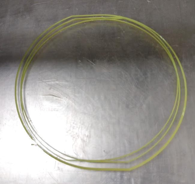
So, still troubleshooting. To try and look more closely at what is happening alignment-wise, I tried printing a simple circle shape:
And here is how the machine printed this shape: https://www.youtube.com/watch?v=NGEXt55Fxww (in this video, I recorded the initial cleaning/leveling sequence in case that could give any clues; the actual print begins at 1:35).
What I notice is that when the machine tries to draw the initial skirt circle, the top and bottom of the circle are slightly flattened (there is a very subtle corner at about 11 o’clock and 5 o’clock). And then of course, when it prints the actual shape the circle is again flattened at top and bottom, but the lines/walls are offset. They actually appear to be mirror images of each other, oddly.
Any other thoughts on what could be causing this offset? Thanks again for your help.
Phil
In advanced settings → backlash, what do you have for X, Y, and Z?
edit: Watching the video - this looks like the Y axis motor shaft-to-gear slipping. Check the set screws for tightness and position on the flat. Belt tension may be very loose, but that’s uncommon. You can see the flat spot of the shaft by looking down directly at the gear. It’s subtle, but easily seen if you’re looking for it.
Also check the printed belt clamp part on the bottom of the bed. It is mounted with two screws, and if one goes missing, the other will hold enough that the bed will move, but the clamp will turn a bit each time the Y motor changes direction. This uses up some of the movement before the bed actually moves, which could give the flat sides on the circles.
One check to help find the problem is to power the printer up, home everything, move the bed to the middle of Y travel with the move menu. Then try to push the bed forward and back. It shouldn’t move unless you push it so hard you skip the motor. If you feel a small amount of free movement, you have something loose like the motor pulley or the belt clamp underneath the bed. Follow the belt all the way around the loop and try to see what is slipping.
3 Likes
@cdsmith It was the missing screw on the belt clamp! I checked underneath, and saw the screw and washer sitting there. It must have worked its way loose. Odd that the event that precipitated this issue was me working with the toolhead, which turned out not to be the root of the problem. I must have jostled the machine around more than I thought when I was working on it. Here is what that belt clamp looks like, for future reference for anyone else troubleshooting y slippage problems:
Anyways, I screwed it back in and my prints appear to be going well/normally now.
@Wrathernaut, thank you for helping me diagnose and figure out that this was a slippage issue. This community is always so supportive and helpful.
People have told me I had a screw loose…I guess they were right 
1 Like
That’s one of my big worries…hearing a screw fall out and trying in vain to find out where it came from (and how it will affect my print). Glad you found it