I have a ton of 2.85mm filament of different types from the fella I bought this from.
If I wanted to upgrade the hot end and nozzle what are some good choices?
Do I move to 0.4mm from 0.5mm? Or stick with the 0.5mm?
To be honest, I really have no idea what diameter nozzle is on this machine. I just took the safe bet and went with .0.5mm for the settings. Since everything was all worn out on this machine I have to think the extruder might have had its share of usage. But who knows for sure.


If staying with 2.85mm filament, the SE Tool Head | 2.85 mm | Single Extruder | 0.5 mm (lulzbot.com) is good, but I printed up the it-works3d parts and converted it to this: IT-Works 3d Titan Aero PRO “X” for Lulzbot 3d Printers - IT-Works 3D (itworks3d.com).
Both of those are limited by the single-gear extruder (stripping PLA), and the other limitations of 2.85mm filament (ooze, brittle). I still prefer to use 2.85mm for flex filaments (and any time I can get 2.85mm at a great price).
Nozzles, if you’re using PrusaSlicer or Cura 5+, you’ve got the arachne slicing engine that will get the detail of .4 pretty easily with a .5 or .6 nozzle. New nozzles I’m only buying .6 from here out. Slice engineer’s bridgemaster and vanadium nozzles are among the best I’ve used, and I use their 1.75mm x .5mm nozzle in my 2.85mm hot end without any issues.
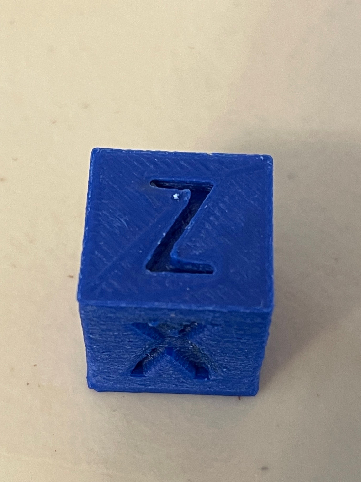
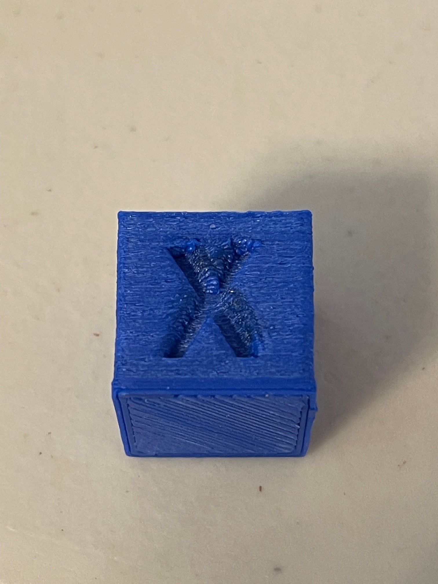
Your cube looks overextruded. Check your esteps, that is not from a lack of an enclosure.
I know my Esteps are off. I do not understand why it lists 2 values and how to change it.
SENDING:M503
echo:Steps per unit:
echo: M92 X100.50 Y100.50 Z1600.00 E833.00 E1800.00
How do I change that value?
103.2 filament is fed when I tell it to feed 100mm.
You change the value with an M92 command, using the values you gave us and this handy calculator the command you want is M92 E807.17.
As for the second E value, I have no idea where that comes from given we know very little about the firmware you have loaded. At the very least, the output of M115 would help.
1 Like
There is most definitely some strange firmware going on… unless he changed it without mentioning it in since the photos - https://us1.discourse-cdn.com/flex020/uploads/lulzbot/original/2X/f/f85538a997773a74baba6825635465a0d2a9bf59.jpeg - it’s marlin from 2014. Documentation on that version is lost to an archive somewhere.
If it hasn’t already been changed, it can be updated to a completely up-to-date version of marlin. Load up Cura LE and load custom firmware, point it to Load firmware for a Taz 5. The one you probably want will be found at “Program Files (x86)\cura-lulzbot 3.6\resources\firmware\Marlin_TAZ5_SingleExtruder_2.0.0.144_aded3b617.hex”
That firmware will only do a single toolhead, so you won’t have to worry about multiple extruder esteps.
Yes, the firmware got updated when I installed the Cura LE. I did the M92 E807.17 and the filament pull was dead nuts on after that. My cubes still looked bad after and my friend said it looked like my nossel was dragging through what was printed smooshing it all around. That explained the weird look of the walls. And that started the discussion on what size nozzle is on there. Cube dimensions when done were still good so I know it is not my z steps.
Maybe I should just cut bait and pick up a new print head so I know everything is good to go. In the meantime, while I am looking at print heads, I will put a new nozzle on this one so I know for sure what its diameter is.
I will upgrade to the latest Cura LE as suggested.
I do not know for sure what diameter print head is on there. With all the wear that was on the machine I suppose the print head could be worn? Do they wear out?
There were all kinds of exotic filaments my Co-worker had that I bought from him for $100. We live in Colorado so I am not super worried about humidity.
Was that a bad deal? I hope they do not have a shelf life and they are still usable. A few are unopened. 2 Rolls of Nijaflex Which I really want to play with at some point.

I will want a print head that can handle all this stuff. Is the It-Works pro X worth the extra 80 bucks from the $300 SE Tool head? If so, why?
Thank you for your support!
Eric
Where on the rambo board is the 5V extruder heat brake fan supposed to be connected to and where is the 24V part cooling fan supposed to be connected to on this rambo 1.3L? I will get those wires ran while I am waiting on a new heater slug. After installing a .4 nozzle the heater gave up.
Start at step 6 here: OHAI: Open Hardware Assembly Instructions (lulzbot.com)
The photos are a Rambo 1.4 but the only changes that really matter are the video cables and the thermistor plug arrangement.
For E0, the 5v heat break fan is the yellow/green in the middle, while the 24v part cooling (Fan 0) is blue/white up top. 24v Case fan is the red/black Fan2. E1 heat break, top left.

Thank you very much. Now I can do some proper wiring tonight and then update my Cura.
What is the latest Cura LE that will work with my Rambo 1.3?
Ok, so Since I am using Heat0 for extruder, Fan 0 would be what the software turns on after the initial layer. That would be the 24v part cooling fan or fans.
Can I put 2 on that same connection in parallel? Just curious.
The 5V fan is what I need to wire up. currently I have a 24V fan on the extruder cooler and noticed it only comes on after the first layer is printed. That makes sense now.
For Do I need X, Y, and Z Max switches to operate the latest Cura LE for rambo 1.3?
I am finally feeling hopeful and excited about this now.
The latest version of Cura LE will use the 1.3 - I’ve got one running daily with it.
To my knowledge, the only differences were to use the more modern standard for the EXP1 and EXP2 blocks for the display, which required moving the thermistor pins, but otherwise, they’re functionally identical.
There shouldn’t be a reason to run two part cooling fans in parallel. Just ditch the axial fan for a 24v 5015 blower and you’ll have more than enough air to cool PLA.
Cura doesn’t care about the switches, but the firmware will. The drivers on the board do not do sensorless homing. To home and calibrate, the firmware requires X-min (print head to left), Y-max (surface forward), and the Z-min (gantry down). X-max and y-min are supported, but during normal operation, should never be hit due to the soft-limits for X and Y. I’m not sure if there’s a z-max in the Taz 4/5.
Thanks! Ill get to going on Cura LE 1.3. and fix the fan situation.
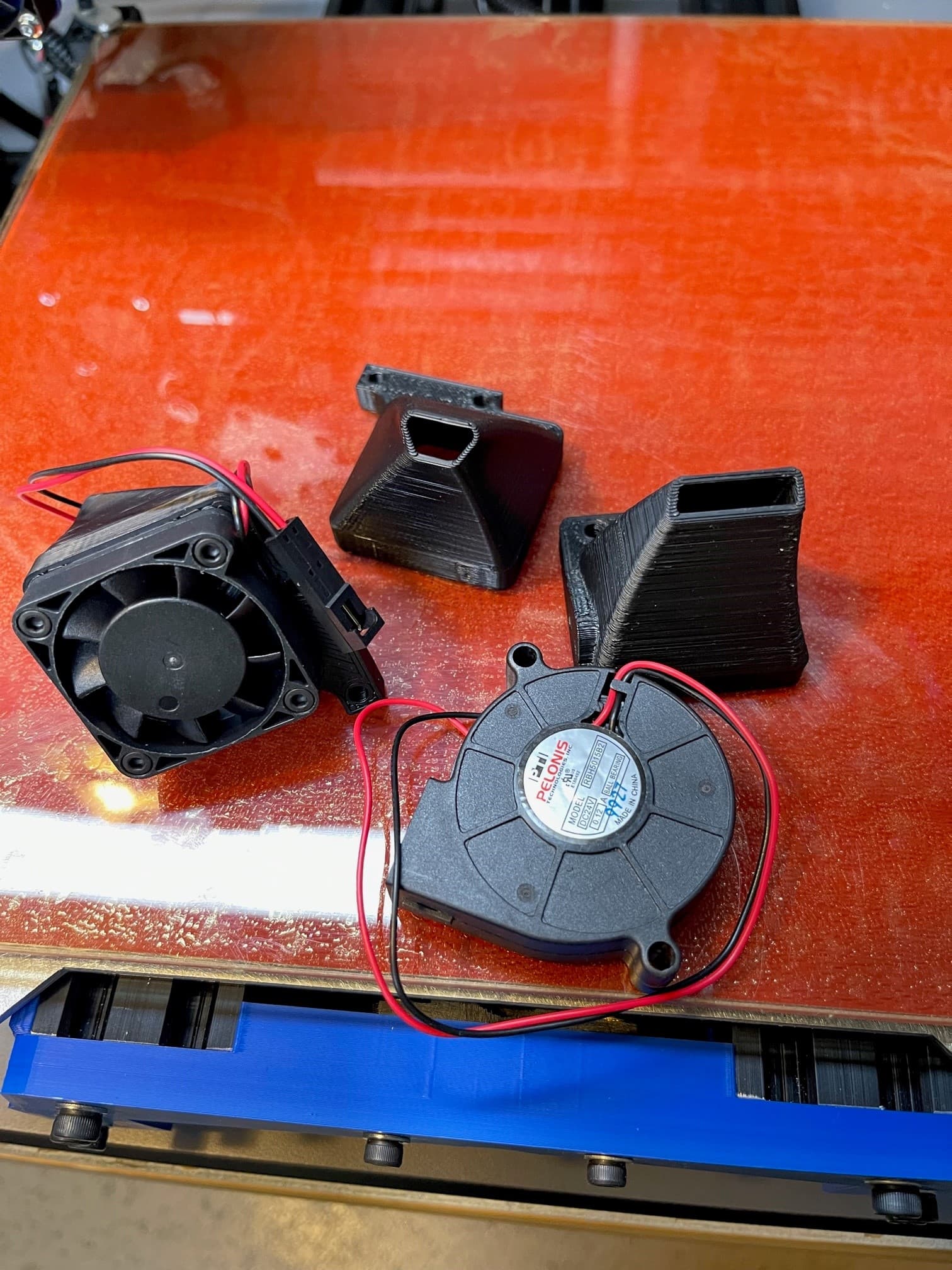
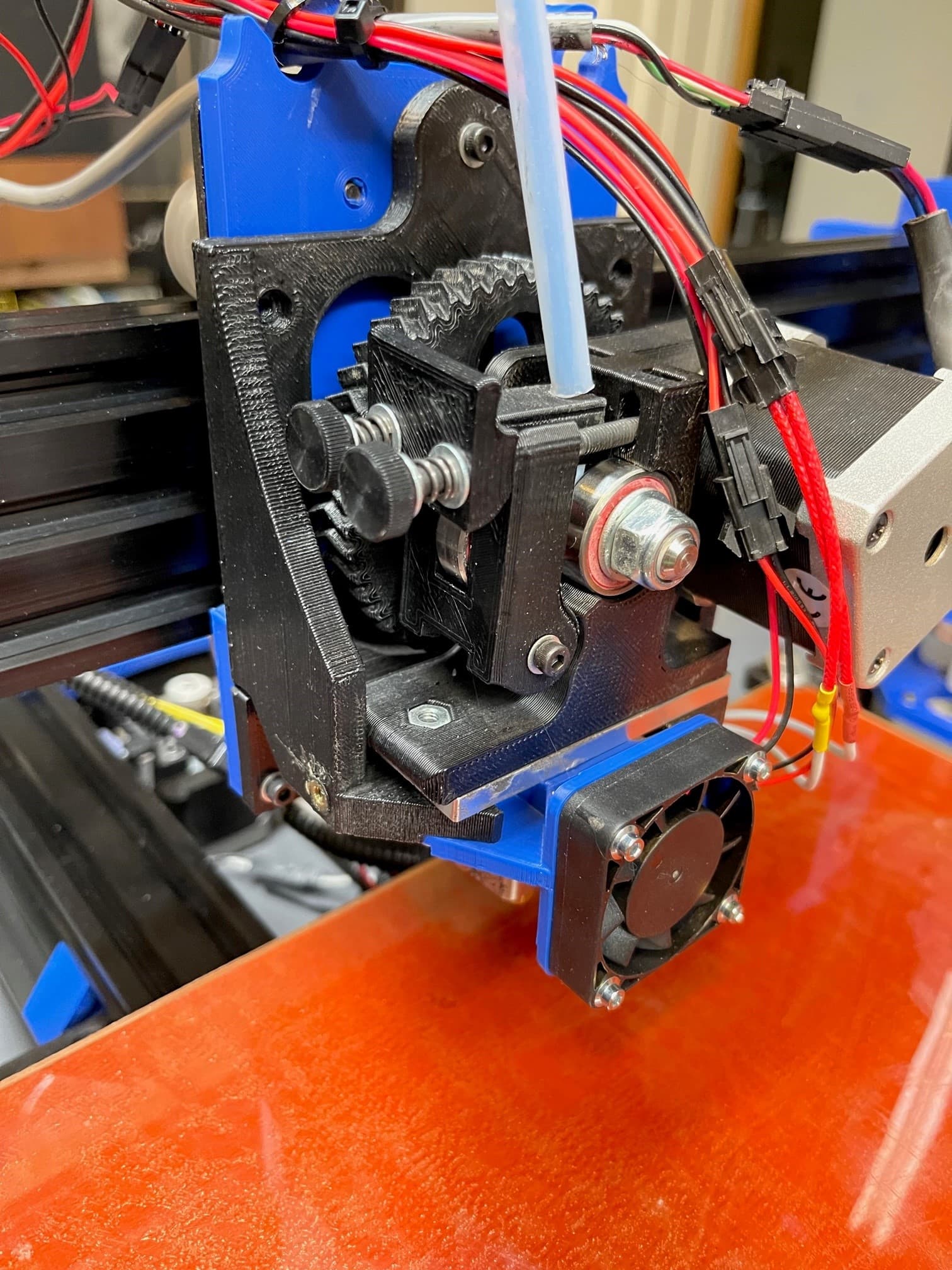
I need to find a mount for my extruder to print that I can add the surround duct part cooling with the 24v blower. The one that is on there now is who knows what. It will not work with any of the ducts I have with the 24V fans. I do have a 24v 5015 blower. I just need to know what to print for the ductwork to attach the fan and the extruder mount that will accept said ductwork.
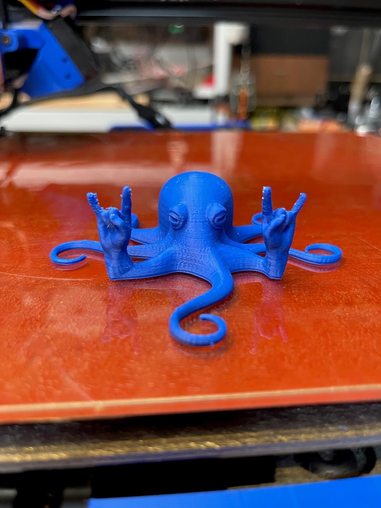
Rocktapus came out way better this time.

Here is what I have for Part cooling options that all do not work with the mount I have:
And here is the mount. This is how it was when I got it.

I am open for suggestions on where to go now. At least I think I can print parts now.
I haven’t seen anything pre-made for a 5015 on a Taz 5 head, but blower fans make enough pressure to get through most half-assed attempts at cooling ducts if you feel like busting out the CAD software.
I installed Cura 3.6.37 which in turn upgraded my firmware to 1.1.9.34.
I have a 0.40 nozzle on the machine and the 3 profile settings show up as
detail 0.15
standard 0.2
high speed 0.35
Are these selectable profiles talking about layer height? I thought for a 0.4 nozzle I should be using multiples of the nozzle. like .10 and .20 and .40 I looked at managing profiles and I do not see reference to the .15, .2, and .35.
I printed an octopus in detail mode and it looks nice.
I am printing the calibration cube in standard mode and it is doing strange stuff like trying to fill in part of the X and Y.

What is up with that?
I want to print out this extrusion mount so I actually have some options to make a part cooling duct.

Will this work for me?
For sure a lot more settings on this version of CURA LE. And evidently I need to set some things I just do not know what at this point.
lol, I figured out what that crap was inside the X and the Y. Support material. lol.
It broke out pretty easily. I got the firmware up to 2.0.0.144 and figured out how to turn support material on and off. I have the 5v heat brake fan installed and wired in and the Part cooling fan wired in. Now I will try and print that extrusion mount so I have a place to mount a part cooling fan. Thanks for the help on the Firmware upgrade 'naut! I will try and stretch out the cooling fan mount to go with the new extruder mount if that ends up working so it is covering the whole heatsink instead of just part of it.
1 Like
I have finally printed something for the printer. I have a little bottle of acetone with a needle applicator that I used to hit some of the layers to make sure they were nicely bonded to make sure there was enough strength to support the print head.
It fit nicely and seems sturdy printed with 80% infill. I do not know how much part cooling is needed for ABS printing. It seems to cool pretty fast. And I wonder if it would harm layer adhesion. I know other stuff likes being cooled so I figured I would get set up for it. Time to print a rock2pus and see how it works.

I am going to attempt to make a new piece for the heat-brake fan. Right now it is only hitting the top half of the hexagon heatsinks. Might as well make the fan exit less restrictive and cover the whole heatsink.
So far so good.
With ABS, it’s generally zero cooling unless you’re doing bridging, overhangs or layers that will be done too fast to allow any cooling. ABS is known for poor layer adhesion, and with a fan going, it’s really bad. I limit my fan to 3% max when doing ABS.
If you’re printing fairly well, you should look into doing some temp towers, fan towers, and other fine-tuning calibration prints
It feels good to have made it this far already! This forum is very helpful! I am glad the rebuild seems to have been worth it.
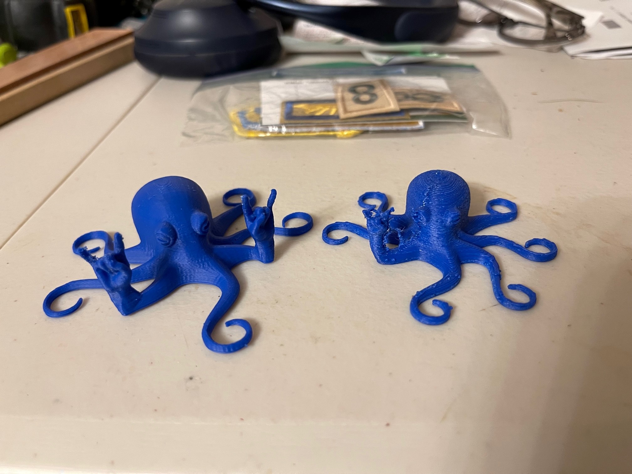
Now that I have a fan setup I can tune the PID for the temp and some of those other fine tuning prints you are talking about Wrathernaut. I have seen examples of 2 towers next to each other. That should help with things like the fingers here.
Temp, retraction, and fans I bet all play a part in this. Ohh and an enclosure. I need to make one of those too. I have an idea using some openrail and clear vinyl sheet. Just something to keep the air still and keep in some heat while still being able to see what is going on.
I hear an enclosure helps a lot. I need to find it a home NOT on my workbench lol.
That’s a huge improvement with just the rocktopus. Blobs are typically a retraction tuning issue, but can also be temperature. With it mostly on the fingers, I’d be inclined to go with general oozing. A combing option might help (can’t remember if this is part of Cura or prusaslicer, or both).
With a 2.85mm tool head, oozing is inherently going to be worse than 1.75, simply due to the higher volume of melted filament in the hot end at any given time.
1 Like