@Wrathernaut I am positive reaction tuning is needed. Going from rods with bushings to plate with v-groove roller wheels on all 3 axis would be a significant change in stepper motor tuning I would guess.
My stepper motors on X and Y get hot. Ya dont wanna hold your hand on them. I will have to get the FLIR out and take a measurement. I ordered a set of nema 17 dampeners and rear heatsinks from Amazon. I figured those could not hurt anything. I am going to cut a piece of 1/2" plywood to make a base and the supports for the enclosure can attach to that. Then I can get it off my workbench. It will make moving it back in there if I need to wrench on it easier.
Has anyone tried this series of tuning tests: https://teachingtechyt.github.io/calibration.html
I figured now that I have fans, once I build the enclosure I could go through all these steps and should have the printer optimized. Unless there is something better out there to use for the fine tuning that is next for me?
Ohh, I changed up the heat brake fan. My hex heatsink is longer than what everyone seems to make cooling fan attachments for. So I made a different one.
Now the whole heatsink gets cooling air from the 5V fan instead of just the top.
I will have to post it on Thingaverse.
My friend gave me a 0.4 and a 0.6 nozzle. I have the 0.4 on there now. How much re-tuning do you have to do if you make a nozzle change? I figured my son would want all these little cute things printed out and the .4 would have better detail so that is why I put that on there. I have some things to print for the shop that are larger and it seems logical the .6 would be better for larger pieces.
Anyone have experiences with both nozzle diameters and comments on them?
If the motors are that hot and the axis moves smoothly by hand with motors off, you need to reduce the current.
What does M503 command report back for your M906 settings?
Teaching tech’s calibration guides are top notch.
The .4 nozzle will increase the pressure, so amplify any stepping and potential heat creep. If you get any issues related to either, switch back to .6mm.
I am wondering if I should wait to perform the fine tuning from Teaching Tech’s calibration guide until after I have my enclosure installed?
I hear enclosures make a big difference. Is that because of holding in the heat or just stopping stray breezes? Maybe a little of both?
Ohh, and was wondering about the PID tuning for the heater. Now I have part fans, but it sounds like ya really do not use fans on ABS. So do I change PID tuning settings along with different filaments since some use more fans than others?
What version of firmware did you end up installing? If you were running a 1.x version of marlin, it will only update to the last 1.x firmware released, so you’d have to manually point it to 2.x, after which it will continue to use the latest 2.x version available. Once you have 2.x going, M503 should report what your current is with the Rambo board. The formula to convert to the digipot units is slightly weird, but pulled directly from the marlin build from Lulzbot: digipot units = ((mA-750)/5+135)
So for any of the Titan Aero-based toolheads or the M175v2 (mA = 875), it’s M906 E160 for the extruder, for the standard extruder (mA = 750), M906 E135. The value for the x, y, and z should be about 800mA, or M906 X145 Y145 Z145
Thinking back, I think I had to use the M907 command instead with the Rambo board, so if M906 doesn’t do anything, do M907 X145 Y145 Z145.
currently I am at 2.0.0.14 for firmware. It says there is another update but I have neglected to do it yet.
It warns you must manually select the nozzle you are using before each print. or something like that.
I am having some binding issues on my Z up at the top. Fixed that and am binding at the bottom now so I am trying to find that happy medium lol. I need to figure out where I am out of square with the Z axis open rail upgrade.
I tried to do a temperature auto tune from a cold start:
M303 C5 S200 U1
It overshot too far and failed. I read that you can change the range auto tune works, and you can change the amount of time the heater is on. This is a big heater for this little block. I tried to adjust some of these parameters but I must not have the commands correct.
SENDING:M303 C5 S200 U1
PID Autotune start
PID Autotune failed! Temperature too high
ok P15 B4
What commands should I send the printer to adjust PID range and or Heater on percentage to help allow an autotune to work? I can print just fine but there is some wiggle during printing of the temp and if that can be adjusted to be better I would like to.
I think I am confused about z offset and z height for the first layer.
I leveled the bed on the TAZ5 (it has the spring loaded corners with cap head screws) using a piece of paper. So now each corner slightly drags on a piece of paper with the bed at 105 and the extruder at 180.
My piece of paper is 0.1mm thick. Now when the machine homes its z zero is really 0.1mm above the bed. Ok so I then go get the Gcode to do these first layer prints from teaching techs website and save the g code and run it from Pronterface. These are the results. I can see in the G code that it sets the Z distance to .4mm which is my nozzle diameter. It does not deviate from that height as it scoots around the print table and you can see it dragged through the center square to get to the last corner.
It set z to be .4 but it really is .5 because zero is really .1. But the results of this test says my Z height is still too low.
So now what? I figured it would show the nozzle is too high but it did not.
So now I know I could raise the screw head that sets the zero but then I have no way of confirming zero and bed level with a sheet of paper anymore.
Is this where I need to use Z offset?
I do not have any way of entering in a z offset on the front LCD screen with Firmware 2.0.0.144.
How do I set the Z offset and where would I start as a setting with these print results?
Thanks!
On my TAZ 6 with firmware 2.0.0.144 I can (view and) set the Z-Offset on the LCD by selecting Configuration, Probe Z-Offset. The current value is shown and can be adjusted up or down by turning the knob.
Maybe I should re-update mine back to something else, then go back to 2.0.0.144. Because that is not there on my LCD screen anymore. It used to be back when I had something in the 1.x.x.xxx.
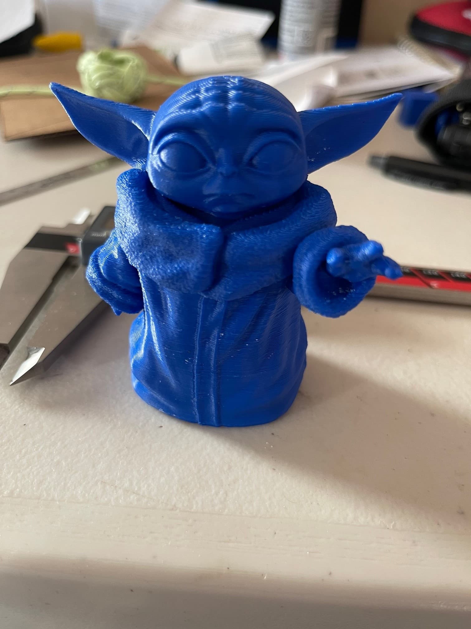
So I found out that the Gcode that gets produced by the generators on the teachingtech will not work on my printer. I tried doing their calibration cube and that was a serious no go. It looked like a weaved basket and was pushing around already extruded stuff. But then, I grab baby Yoda from Thingaverse, use Cura LE to slice and it comes out beautiful. I printed up a baby Yoda with supports and it looks really nice. I would still like to tune and find out where my machine limits are. I could be printing right now at half speed or something. lol. Who knows.
There must be a chunk of G-code I need to insert in front of the Gcode that the teachingtech website is producing maybe?
It is like it is over extruding big time with their gcode. Which would explain the first layer print test not doing what I expected. Any ideas on why what what I should do?
CuraLE (and most other slicers) have start gcode, end gcode, and possibly other situational gcode scripts. These scripts are printer specific so there is a good chance that if you are downloading gcode, it will have to be modified.
For the teaching tech calibration you need to check the box to only use your startup gcode, and use the startup gcode produced by Cura LE with the filament you’re using. The start gcode box in machine settings has some variables that are filled in with material settings for wipe, soften and probe temperatures.