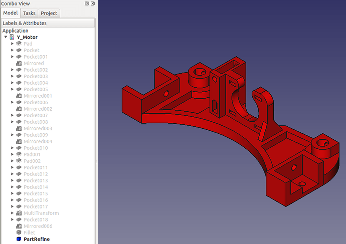
how to modify FreeCad files

I’m trying to turn my MendelMax 1.5 into a Taz. I really like the design of the Taz and how it can fold away. I’m going to be living away from home for a few months and obviously I want to take my printer, so I am finding ways to make it smaller :smiley:

My plan is to re-use the extrusions and rails from the mendelmax. My x and y rails are only 8mm, so I’ll need to modify some parts to get them to fit. I’ve not used FreeCad before, and I’m having trouble working out how to modify ‘Y_Motor.fcstd’ to change the rod diameter to 8mm - is this easily done?

thanks!

Hello badger,

I modeled the original TK-0 FreeCAD files when the TAZ was still in development. I believe this part is unchanged, at least here in the Dowloads section. http://downloads.lulzbot.com/lulzbot/TAZ/hardware/printed_parts/FreeCAD/FCStd/

First it is important to mention which version of FreeCAD you installed, and on what operating system. The easiest way to do so is to go to the Help menu, then “About FreeCAD”, and click on the “copy to clipboard” button. Paste the content here.

To be honest FreeCAD’s got a steep learning curve, if you have no prior CAD experience you might struggle with this. Plus FreeCAD suffers from its lot of quirks and bugs.

In any case, here’s a short intro.

FreeCAD is a parametric modeler, and all operations to create a part, called “features”, are listed in the Project tree at the left.


You can explore the history of the part by toggling on/off these features. Currently the last one at the bottom is the only one visible. Select it in the tree, and press spacebar. It will be hidden from the 3D view. Now select the top feature named “Pad” and press spacebar again to display it. You will see that this part started out with a simple rectangle that was extruded (or padded, in FreeCAD’s terminology). You can try and toggle visibility of each feature (only display one at a time) until you locate the one that adds a hole for the smooth rod.

At some point you’ll find the feature adding the smooth rod hole is Pocket008. (I could have renamed all the features to make them easier to distinguish :unamused: )

Click on the marker in front of Pocket008 to reveal the sketch underneath.


Double-click on Sketch010 to go into sketch edit mode.

You will see that this sketch contains a circle, and a radius dimension of 5.30. Double-click on the label in the 3D view, or on the “Constraint5 (5.3)” listing at the bottom of the Tasks panel. This will open a small dialog to edit the value.

After that you click on “Close” in the Tasks panel to exit sketch edit mode.

Now, depending on which FreeCAD version you’re using, you may find quite a few features got a red exclamation point on them. That means they failed to update, and they’ll have to be rebuilt.

Depending on how much time you’re willing to spend on the CAD side of things, we could do this “the lazy way” instead, by disregarding the part history, and plugging those holes then cutting new ones. That may save you a lot of grief…

And BTW, the best place to get help on FreeCAD is on the FreeCAD forum, which just moved this week. http://forum.freecadweb.org/ I’m an admin, and I’m always there. :ugeek:

Hi Gemini64,

Wow, thanks for taking the time to write such a detailed reply!

I’m using FreeCad on Archlinux:

OS: Linux
Platform: 64-bit
Version: 0.13.$WCREV$
Python version: 2.7.5
Qt version: 4.8.5
Coin version: 3.1.3
SoQt version: 1.5.0
OCC version: 6.6.0

I had worked out most of what you’d posted, and changed the constraint, but as you mentioned a few features had the exclamation point, and the hole did change in size.

I’ve used OpenSCAD a lot for my 3D printing adventures, and this is perhaps where it really shines - making a small modification! but my knowledge of ‘normal’ 3D cad is fairly minimal.

I’ve tried opening the features with red exclamation point and OKing them, but eventually FreeCAD crashes :frowning:

I’ll have a go at the ‘lazy way’; I like lazy ways :sunglasses:

thanks again for your help!

I don’t know what is it with some Linux distros, but obviously the build process does something wrong. That $WCREV$ should actually be a 4-digit revision number. So I have no idea if your FreeCAD is based on the v0.13 stable release, or the v0.14 development branch which I currently use and which for a time was still labeled v0.13.

Would you care to give me details on where your FreeCAD version comes from? Did you compile it yourself? I’ve seen the same problem with the Fedora build, and I’d like to talk to one of the FreeCAD devs about it. I don’t have the knowledge to fix this, but he does. Maybe it’s some config file that needs to be changed in the source code.

If your FreeCAD is based on the development branch from the past few months, there may be two problems at work.

One is that between v0.13, which I used to create the TK-0 files back in January, and v0.14, there’s been changes in how transformation tools such as Mirrored or Pattern features work. And I’ve used those profusely. When opening those files on v0.14, the transformation features all need to be fixed (which is easy), the hole change has no effect on this.

Pro-level parametric CAD software is generally more stable than FreeCAD and such a small change should not create problems. The second problem I was alluding to earlier is that Part Design feature editing is currently FreeCAD’s Achilles’ heel and not much is needed to bork a model. I’ve had to rebuild those TK-0 parts quite a few times. The reason for this weakness is technical and I won’t explain it here (I barely understand it :wink: ), but the devs are working at fixing it for v0.14.

I would say that FreeCAD’s code is a lot more complex than OpenSCAD’s, and working on scripted parts that need to be recompile after each change is a lot more forgiving. In FreeCAD, the part is updated automatically after each edit.

But if I had built my parts using a CSG method similar to OpenSCAD, my models would be a lot more robust to changes. Except I dislike that method which I find primitive, time consuming and more prone to errors, as you need to set your primitives’ coordinates in the 3D space.

Also, I should have mentioned that the last feature at the bottom of the tree, labeled “PartRefine”, is not parametric. I produced it with a face clean-up tool from the Part workbench, something one of the FreeCAD devs added because of an Open Cascade bug. Open Cascade is a third-party library used for the CAD kernel, and the FreeCAD devs have unfortunately no control over it. So you should delete that feature because it won’t update with the hole size. (in the latest source code it has been integrated into Part Design tools so the end user won’t need to run it anymore)

This post has grown quite long :blush: , to get back on topic I think I’ll follow up in a new reply.

Hey, I just noticed that Lulzbot have been updating files for the TAZ. There’s a new Y_Motor file here.

http://devel.lulzbot.com/TAZ/2.2/production_parts/FreeCAD/
I’ll have a look at it and report back.

Edit: I can download that file, there’s a permission problem…

2nd edit: I inquired about it here: http://forum.lulzbot.com/viewtopic.php?f=16&t=436

Thanks again for your help.

The FreeCAD I was using was compiled from source, it looks like version 0.13.1830.

I just checked out the latest FreeCAD code from git and built that. It behaved differently but still had problems.

It seems that even without making changes FreeCAD can crash when re-applying the features. I’ll try a windows version later.

I’ve had more success with the windows version (FreeCAD_0.14.2370_x86_RC_setup).

I’ve managed to change the hole radius, and even got it reflected in the 3d model :sunglasses:

But, I’m not able to apply some of the previous features.

For example:

Neither of the plane options mirror this part to the otherside as it should :cry:

I’m nearly there!

I started from the beginning and opened each part, then applied each pocket etc in turn. I made a few modifications - rod diameter as well as the diameter for the inserts as I can only find 4mm OD ones.

Towards the end a couple of things messed up - the square bolt holes for the motor and a couple of square holes on the feet (I can’t work out what these are for!).

I’ll now learn how to use FreeCAD so I can tidy up the motor mount :smiley:

I had a go at reducing the width of this part as it is right at the limit of what I can print currently, but some of the constraints are made on the assumption of the part being 200mm wide, so its not that easy :cry:

If I make a ‘minor’ modification am I meant to have to apply each action after it for it to take effect? or is there some sort of ‘redraw’ command?

Sorry to leave you hanging. Yeah, there’s been heavy changes to FreeCAD between the time I modeled these parts and the latest unstable version.

Now I remember, at the time I made this, the mirror tool could use global planes such as XY, XZ and YZ. I was using a development release of v0.13, and when the stable version was release in February the mirror parameters had been changed to only accept the sketch axes or an external geometry (edge). This means that this feature could not be mirrored that way anymore.

No idea either. I just modeled those parts based on Sketchup files Lulzbot had at the time.

It’s very odd that you had so many crashes in ArchLinux. It’s pretty stable on Ubuntu.

Yes, many sketches would need to be changed.

I couldn’t print this part on my AO-100, I only have a printable surface of 185x190mm.

I can just about fit it on my 190x195 bed with the part rotated 45 degrees. I’m going to have a go at butchering the STL with OpenSCAD and scaling the sections between the feet and the motor mount. It wont be pretty but it should work :laughing:.

Do you have any tips regarding my last comment - how to apply an update and ‘redraw’ the model? Perhaps this doesn’t happen automatically because of other problems.

Let’s say I wanted to reduce the width of this part properly using FreeCAD.

I modify the constraint to set the width to 160:

When I get to sketch002 the constraints are messed up:

compared to the original:

What are my options here? can I alter the constraints without creating a new sketch? or should I just consider this the limit of what I can change without re-creating the model?

thanks for your help!

Can you share the modified fcstd file? Since you already rebuilt it I would like to avoid the work. :wink:

The idea is to go back to each sketch and fix it. But I’ll know more with your file. The one I have here is useless because of all those failed mirrored features…

Of course! here it is.

I’ve not fixed the motor mount yet.

Thanks.

Unfortunately, that model is shot to hell. The Mirrored001 feature fails as soon as you edit it. It’s for the reason I explained earlier, the Pocket005 feature which the mirrored feature is based on cannot be mirrored that way anymore. It has to be replicated manually on the other side.

Stay tuned, I’m rebuilding that part from scratch. This time, I’m using a single sketch and pad to recreate what I did with 5 features. I’m counting on having less sketches and features so that it’s not such a headache to edit the part.

I can’t wait for v0.14 final to come out, those problems should be mostly fixed then.

Oh boy. I’ve been going over the Y_Mount part and I’m sorry to admit that it is very badly modeled. I pride myself as being a FreeCAD guru, quite a nice dose of humility here! :smiley:

If that part had not been half-arsed, you wouldn’t have had half the trouble you’ve had with it so far. I can only hope all the other parts aren’t half as bad. :blush:

FreeCAD due to its “unfinished” nature has weaknesses, but they are compounded by the way I built the part. Makes the software look bad and I don’t like that!

So I’m completely changing the way it’s modeled. I’m trying to make sure the most important features are built as early as possible, and that one can change only one dimension to change the distance between the smooth rod holes, with everything else following. I still have a lot of features to go, but for now it’s working.

I hope you can wait! I don’t know if I’ll get done tonight.

Okay, I’ve got a version here that won’t break as easily, provided you don’t hit it too hard. :smiley:

Y_Motor_rebuilt_v4.fcstd

To simplify the part, I started it as only half of it, since it’s mostly symmetric, then I applied a Part Mirror which mirrors the whole body rather than just a feature.

To change the smooth rod hole diameter, look for the sketch underneath the “Smooth_rod_hole” feature.


To change the total width, open the sketch under the first Pad, and change the 100mm value.

Keep in mind this value is half-width. Reduce the value repeatedly by small increments, if you make too big a change the model will break. I was able to successfully go down to 90 by changing from 100 to 95, then to 93, 91, and 90. When you see that the model gets weird, close it and reopen it, and try again.

In an attempt to make the model more robust I modeled the motor mount as a separate part, and boolean fused it later on. I had no choice but to add successive features on top of the fused solid though.

I’m not completely happy with it, I’d like to have control over the width as well as the distance for the smooth rod hole from the center axis in the same initial sketch, so I might give it another shot tomorrow.

Then again, I may wait to get access to that modified Y_Motor file in the devel repo and see what’s been changed before going further.

P.S. With the latest source, the Part Refine shape tool is no longer necessary! :slight_smile: You just need to set your preferences in Part Design/General to “automatically refine model after sketch-based operation”.
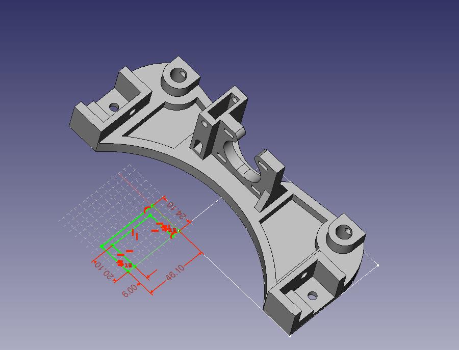
Thanks for going to all that effort, it is much appreciated :slight_smile:

I seem to be having a lot more issues with FreeCAD than you… all I’ve done is open the model, double clicked the top feature ‘Pad’, clicked Ok, then opened Pad002 -> Sketch002. The sketch gets shifted about:


Which version of FreeCAD are you using? None of the edits I’ve made have been successful, but maybe I’m doing them wrong :confused:

Man I have no clue what’s going on at your end. :confused: I just tried what you said, and the sketch didn’t shift.

My details follow:

OS: Ubuntu 12.04.3 LTS
Platform: 64-bit
Version: 0.14.2727 (Git)
Branch: master
Hash: b035e9cb0cc6817bdc1ad0eb83de23a4ab3c52dd
Python version: 2.7.3
Qt version: 4.8.1
Coin version: 3.1.3
SoQt version: 1.5.0
OCC version: 6.5.0


Orias fixed the forbidden access error to the latest Y_Motor_v1.1.d.fcstd file in the devel.lulzbot.com repo, so I had a look at it. There’s a small change with the motor mount bracing. They also added discs at corners to prevent the bottom layer from warping.


They did a good job, for example they completely removed the transformation features in an attempt to make the model more stable. But if you change the overall width, the model goes poof like my original.

Also, since my last post last night, I’ve started over yet again :smiley: , I’m now at version 6 but it’s not finished. This one seems a lot more robust. I may make changes yet again though!

If at first you don’t succeed… :wink:

Got it! See the following video. :ugeek:

I haven’t had the time to add the discs at the corners to prevent warping, I’ll try to do that tomorrow.

Y_Motor_rebuilt_v7.fcstd (348KB)

That all looks perfect in the video! Thanks for making that, it looks like I was editing the constraints in the same way. Unfortunately the Ubuntu One links don’t work - even the one that did work yesterday :cry:

I’m looking at the differences in our FreeCAD versions:

OS: Linux
Platform: 64-bit
Version: 0.14.2727 (Git)
Branch: master
Hash: b035e9cb0cc6817bdc1ad0eb83de23a4ab3c52dd
Python version: 2.7.5
Qt version: 4.8.5
Coin version: 3.1.3
SoQt version: 1.5.0

They are very similar, but mine doesn’t include anything about OCC. So I’ll look into that!

I managed to download the file :sunglasses:

But once again my various version of FreeCAD do not behave like yours does! I’m going to install ubuntu 12.04 on a spare partition (been meaning to do that anyway) so I can avoid OS related issues.